Mueller Bakery Chiller, Models PMC 40/50 and PMC 70/120 Effective February 23, 1999
Installation and Operation Manual, Part No. 9842311 Revised October 17, 2019
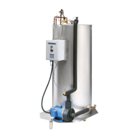
2.5 CONDENSING UNIT INSTALLATION
All refrigerant piping should be in accordance to acceptable refrigeration practices. Distance between condensing
unit and bakery chiller assembly should be as close as possible. Long distance piping and risers may require
attention to reduce restriction of refrigerant flow and to provide adequate oil return.
The liquid line should be
3
⁄8" OD copper pipe and the suction line
7
⁄8" OD copper pipe. A liquid line drier of adequate
size should be installed on all PMC 40/50 RC and RS models. A liquid line drier is provided on 3.5 HP condensing
units for PMC 70/120 RC and RS models. A liquid line sight glass should be installed just prior to the thermal
expansion valve (TEV) on the bakery chiller evaporator assembly. Attach the TEV sensing bulb to the suction line
and insulate after refrigerant lines are installed, as shown in Section 7.3 and Figure 7.
Evacuation to 500 microns prior to refrigerant charging is required. The system must hold 1,000 microns in a
standing vacuum test, ensuring that it is leak free.
Initial refrigerant charging should be through the liquid service valve, as most blended refrigerants must be charged
in liquid form only. Charge with an adequate amount of refrigerant prior to starting the compressor and make sure
the water storage tank is filled with water. Refer to Section 3.0 for startup procedures.
4