Mueller Bakery Chiller, Models PMC 40/50 and PMC 70/120 Effective February 23, 1999
Installation and Operation Manual, Part No. 9842311 Revised October 17, 2019
2.1 INSPECTION
Because it is possible for equipment to be damaged during shipment, Paul Mueller Company recommends
thoroughly inspecting the equipment before it is unloaded from the freight truck. Carefully examine the equipment
for concealed damage. It may be difficult to collect for damage if it is not found prior to unloading. It is important to
note any damage on the bill of lading and have the driver sign it.
2.2 SAFETY
The installation and service should be performed by an authorized service technician with the proper training to
install and service refrigeration equipment. Effective November 1994, the service technician must be certified in
refrigerant usage by a testing organization approved by the U.S. Environmental Protection Agency (EPA) before
installing or servicing refrigeration equipment.
All electrical connections must be performed by a qualified electrician in accordance with the National Electric
Code and local regulations.
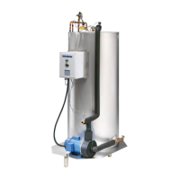
2.3 LOCATION
When choosing a location for the Mueller bakery chiller, consider these items:
• Environment: The Mueller bakery chiller should be located indoors where the chiller section is protected
from freezing temperatures.
• Serviceability: The bakery chiller should be located with the circulating pump and the control panel
accessible for service. Keep in mind the chiller will require field connections to the main electrical supply and
water supply line. The chiller should be located close to a drain for service and cleaning.
• Condensing Unit: The condensing unit (for RC bakery chiller models) must be located where it is protected
from the environment and have adequate air flow for the condenser. Be especially cautious of conditions
allowing dust or oil to enter the condenser.
• Efficiency: Locate the bakery chiller as close as possible to point of use for chilled water.
2.4 CHILLED WATER PIPING
The bakery chiller supply water should be connected to the
3
⁄4" inlet water solenoid valve located at the top of the
water tank (refer to the flow diagrams, see 5.2 and 5.3). The supply water line should be taken from a source that
provides adequate water flow and is a minimum of
3
⁄4" in size. It is recommended a full-flow shut-off valve and
union be installed just prior to the solenoid valve for service.
The chilled water supply should be connected to the
3
⁄4" chilled water outlet located near the circulation pump.
Keep this line as short as possible to allow for chilled water of the desired temperature to be provided to the point(s)
of use. This line should be insulated to reduce external heat gain to the chilled water.
Check all piping for leaks and repair if required. Clean and rinse lines and water storage tank prior to usage.
3
Section 2.0 – Installation