Mueller Bakery Chiller, Models PMC 40/50 and PMC 70/120 Effective February 23, 1999
Installation and Operation Manual, Part No. 9842311 Revised October 17, 2019
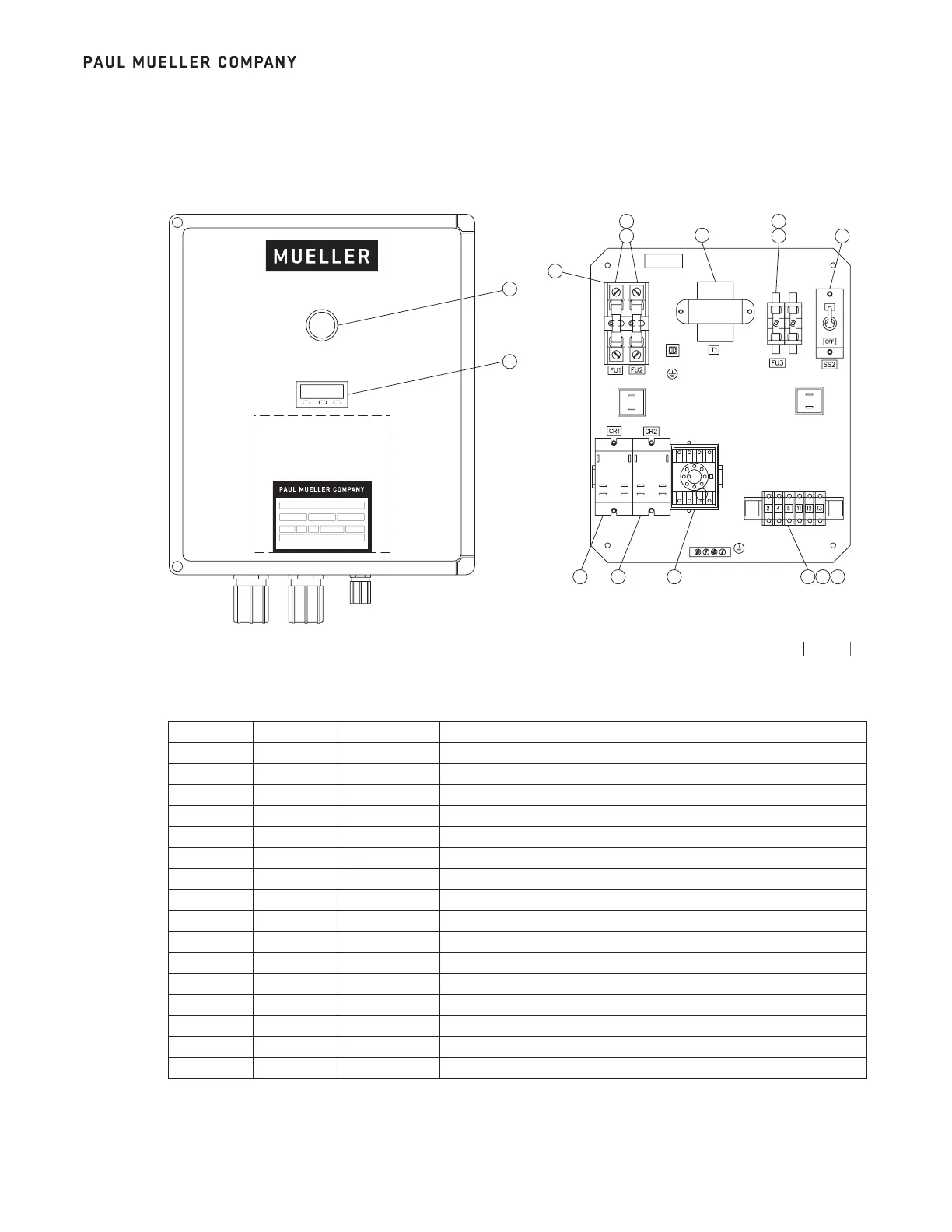
6.1 CONTROL BOX
6.2 CONTROL BOX PARTS LIST
11
Section 6.0 – Parts Illustrations
PRODUCT
MODEL NUMBER PART NUMBER SERIAL NUMBER
VOLTS HERTZ
PHASE
LRG MOTOR AMPS
FLA
DISCONNECT MAIN POWER SUPPLY BEFORE SERVICING.
ROMPRE LE CABLE DE DISTRIBUTION AVANT DE REPARER.
1706 30890
FRONT VIEW
2
1
CR0005
BACK PANEL LAYOUT
3
6
5
7
4
8
12
9
10 11
13
15
13
Item No. No. Required Part No. Description
1 9842292 Control Box Assembly, Bakery
1 1 9844261 Controller, Temperature
2 1 9842305 Switch, Push Button, Lighted
3 1 8820718 Transformer, 208–240 V, PRM, 24 V Second
4 1 9844317 Liquid Level Control Module
5 2 9820091 Fuse Block, 30 Ampere, Class CC
6 1 505793 Barrier, Electrical End Fuse
7 2 9823754 Fuse, Cartridge, 7 Ampere
8 2 8820703 Fuse, Block, 30 Ampere
9 1 8806523 Fuse, Cartridge, 2 Ampere
10 6 8805635 Terminal Block
11 1 8805636 Barrier, Electrical End
12 2 8805226 Clip, Retainer
13 2 8820240 Relay, Switch, DPST, 24 VAC
14 1 8820165 Thermocouple, Sensor, Type “T”
15 1 30853 Switch, Toggle, DPST
 Loading...