Mueller Bakery Chiller, Models PMC 40/50 and PMC 70/120 Effective February 23, 1999
Installation and Operation Manual, Part No. 9842311 Revised October 17, 2019
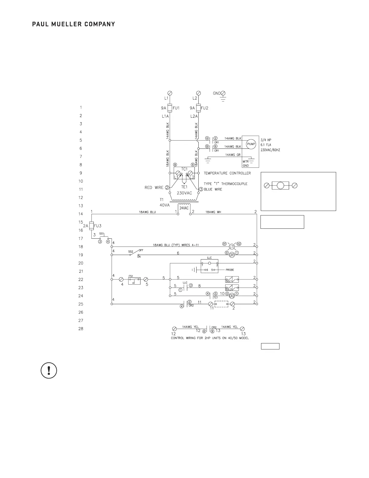
5.1 WIRING SCHEMATIC, PART NO. 9842313
IMPORTANT: A type “T” thermocouple is provided for the temperature sensor. It is important that the
thermocouple wires are properly connected to the temperature control. The constantan (silver) wire is to
be connected to terminal 2 on the temperature control. The copper wire is to be connected to terminal 3
on the temperature control.
9
Section 5.0 – Diagrams
230VAC
For Mueller “OE” series condensing units,
connect 11 and 2 on chiller control terminal
strip to 2 and 4 on condensing unit.
211
M
CONDENSING UNIT
START (24VAC)
STANDARD CONTROL
PROCESS WATER OUT
FLOW SWITCH
LEVEL SWITCH
START SWITCH
PUMP DISABLE SWITCH
REFRIGERATION
CONTROL DETAIL
RECIRCULATION SOLENOID
SYSTEM OPERATION LAMP
FILL SOLENOID
CONDENSING UNIT
START DRY CONTACT
PUMP MOTOR START 5,6
LIQUID LEVEL CONTROL RELAY
21, 23, 24
REFRIGERANT CIRCUIT RELAY 25, 28
REFRIGERATION CONTROL
CONNECTIONS (SEE DETAIL)
9842313
9001759-D REV. S
CR0004