Video Grabber DisplayPort User Manual - ver. 1.2
2.1. Device Status Screen
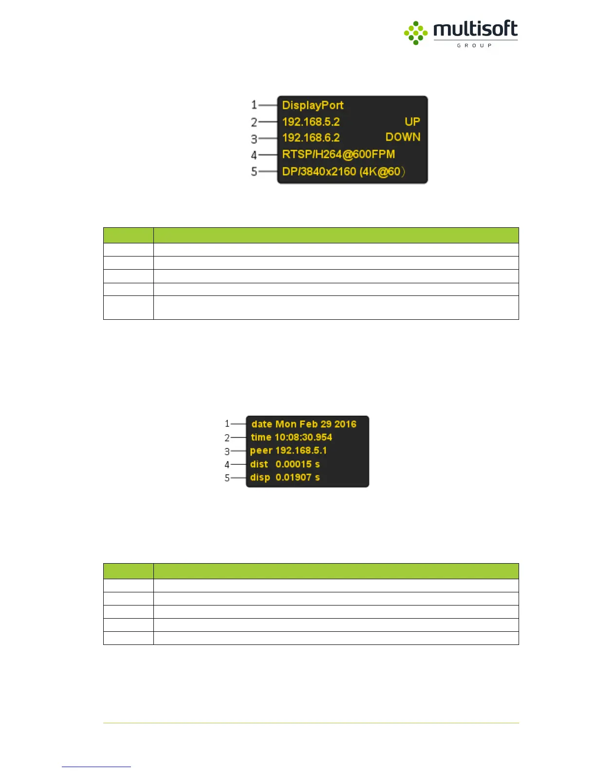
Figure 3. Device status screen
Table 3. Device status screen description
2.2. NTP Status Screen
Figure 4. Device NTP status screen
Table 4. Device NTP status screen description
Device description - it can be changed using Video Grabber’s Web management console
IP of the first interface (LAN 1), UP indicates active link, DOWN indicates no active link
IP of the second interface (LAN 2), UP indicates active link, DOWN indicates no active link
Current settings of transmission
Detected signal displayed in format signal type / resolution. In case of unrecognized or lack of signal Looking
for signal… is displayed
IP of connected NTP server
Distance, time between sending and receiving NTP packets
Dispersion, maximum offset error