3.2. Connecting video signal
Video Grabber has two DisplayPort connectors, one for input and one for output video signal. Connect
source signal to Video Input, and display to Video Output. It is strongly recommended to use good
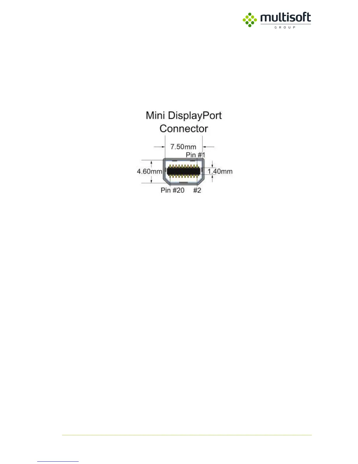
quality cables with DisplayPort pin 20 connected on both side of the cable to power video splitter in
case of device power failure.
Figure 6. Mini DisplayPort Connector
NOTICE: For highest resolution (up to 4K) please do not use cables with total length more than 2
meters (1 meter from source to device and 1 meter from device to monitor). Using longest cable may
lead to signal degradation, signal distortion or loss the signal.
3.3. Network connection
Video Grabber has two rj45 ports, named LAN 1 and LAN 2. The same network traffic is generated on
both lines. Most often LAN 1 is connected to server A, LAN 2 to server B. It’s possible for Video Grabber
to work on only one network interface but it’s not recommended due to lack of redundancy. That
minimizes the risk of losing important data due to hardware or software failure. Device can work in
100 Mbit/s network depending on frames per second, resolution and output format used, but better
to connect to 1 Gbit/s network in order to be able to achieve higher data rate. Video Grabber detects
type of network automatically. Network connection cable must keep network standard of minimum
category 5e.
The specification for category 5 cable was defined in ANSI/TIA/EIA-568-A, with clarification in TSB-95.
These documents specify performance characteristics and test requirements for frequencies up to 100
MHz. Cable types, connector types and cabling topologies are defined by TIA/EIA-568-B. Nearly always,
8P8C modular connectors (often referred to as RJ45 connectors) are used for connecting category 5
cable. The cable is terminated in either the T568A scheme or the T568B scheme. The two schemes
work equally well and may be mixed in an installation so long as the same scheme is used on both ends
of each cable.