EasyManua.ls Logo

MULTISPAN AVH 14N-M1 User Manual

MULTISPAN AVH 14N-M1
5 pages
To Next Page IconTo Next Page
Page #1 background imageLoading...
Page #1 background image
Multispan Control Instruments Pvt Ltd
72/B, Phase 1, GIDC Estate, Vatva, Ahmedabad-382445, Gujarat, India.
www.multispanindia.com
+91-9978991483
export@multispanindia.com
AVH 14N-M1
User Manual
ENVIRONMENT CONDITION:
INPUT:
Direct Voltage AC
30 to 300V(L - N)
50 to 500V(L - L)
Burden
Voltage AC
Current AC
Burden
Primary CT Ratio
Secondary Current AC
Overload
Frequency
Up to 6A continuous
45.0 to 65.0 Hz
< 0.2VA
5 to 6000 Amp selectable
< 0.2VA
50mA to 5 Amp Direct
3 Phase - 3 Wire, 3 Phase - 4 Wire
(Network Selection)
Supply Voltage
100 to 270V AC, 50/60 Hz
Power Consuption
4VA @ 230 AC MAX
AUXILIARY SUPPLY:
Size (mm)
Panel Cutout (mm)
96 (H) X 96 (W) X 52 (D) mm
92 (H) X 92 (W) mm
DIMENSION:
Display
Upper: 6 Digit, 7 Seg 0.40”,RED LED For KWH
LOWER: 4 Digit, 7 Seg 0.40”,RED, 3 Line
Keys
SET/ENT, INC, DEC, RESET
DISPLAY AND KEYS:
Technical Specification
Protection Level
(As Per Request)
IP-65 (Front side) As per IS/IES
60529 : 2001
Operating Temperature
0°C To 55°C
Relative Humidity
Up to 95% RH Non Codensing
Terminal Diagram
1 2 3 4
7
8 9
12
13
14
10
11
5
1617
181920
6
15
S1 S1 S1 S2S2S2
R
Y
B
Range:
Current: 50mA To 5A AC
Voltage (P-P) : 50-500V AC
(P-N) : 30-300V AC
VR
VY
VB N
L N
!
Made in India
www.multispanindia.com
100
270V AC
~
50/60 Hz
4VA
CAT III
* The maximum demand value is the maximum average
value of the instantaneous power during a defined time
interval set in MD Time parameter. The default value of
MD time is 15 minutes, which is selectable.
Maximum Demand
To select connection press key and power on the
instrument.To save the connection power off the
instrument.
Wiring Connection
RESET
Change by
key
3 Phase/3wire
3 Phase/4wire
Upper Display
Lower Display
RESET
Parameters
Parameter Display
Phase Neutral Voltage (Vpn)
30 - 300 V
50mA -5A (Direct without CT)
50 - 500 V
0.000 - 9999 KW
0.000 - 9999 KW
000.000 - 999999 KWh
000.000 - 999999 KVAh
000.000 - 999999 KVArh
0.10 - 1.00
0.10 - 1.00
0.000 - 9999 KVA
9999.59 Hrs/Min.
0.000 - 9999 KVAr
3000 RPM
45 - 65 Hz
9999.59 Hrs/Min.
Line CURRENT ( ~A )
Line Voltage (Phase-to-Phase) (Vpp)
Active Power ( KW ) Total
Active Power per Phase(KW)
Active Energy ( KWH )
Apparent Energy ( KVAh )
Reactive Energy ( KVArh)
Power Factor ( PF ) Average
Power Factor per phase ( PF )
Apparent Power (KVA )
Load hours
Reactive Power ( KVAr )
RPM
Frequency ( Freq )
No load hours
Measurement Range
MD KW
MD KVA
MD KVAr
0.000 - 9999 KW
0.000 - 9999 KVA
0.000 - 9999 KVAr
C O n e
C O n e
3 P 3 w
3 P 4 w
D+
MODBUS
D-
System : 3 Ph-4W,
3 Ph-3W
Accuracy Class: 0.5
Question and Answer IconNeed help?

Do you have a question about the MULTISPAN AVH 14N-M1 and is the answer not in the manual?
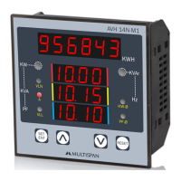
MULTISPAN AVH 14N-M1 Specifications

General IconGeneral
ModelAVH 14N-M1
CategoryMeasuring Instruments
MountingPanel Mount
DisplayDigital LED
Measurement Range0 to 600V AC
Accuracy±0.5%
Power Supply230V AC, 50/60Hz
Weight250 g

Summary

Technical Specification

Input Specifications

Details electrical input specifications like voltage, current, frequency, and CT ratios.

Display and Keys

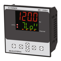
Describes the device's display capabilities and user interface keys.

Physical Dimensions

Provides physical dimensions and panel cutout sizes for installation.

Auxiliary Supply

Specifies the required auxiliary power supply voltage and consumption.

Environment Conditions

Outlines operating conditions like protection level, temperature, and humidity.

Parameters and Measurement Ranges

Parameter Display Details

Lists parameters shown on the device display and their corresponding measurement ranges.

Modbus Parameter Selection

Modebus Menu Navigation

Guide to entering the Modbus menu and configuring parameters like address, baud rate, and parity.

Modebus Communication Settings

Details Modbus parameter configuration options including address, baud rate, and parity.

CT Selection Procedure

CT Ratio Configuration

Steps to select and configure the Current Transformer (CT) ratio for accurate readings.

Load Hour and RPM Settings

Procedures for enabling/disabling load hour and RPM functionalities.

RS-485 Communication Registers

Read/Write Function Registers

Lists Modbus registers for reading and writing various electrical parameters and settings.

Communication Protocol Details

Specifies Modbus communication settings: device address, baud rate, parity, and data types.

Application Notes

Important notes on meter usage, external CT selection, and accuracy considerations.

Display Pages Overview

Page 5: Voltage and Frequency

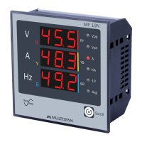
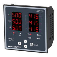
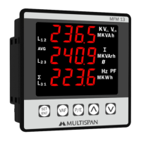
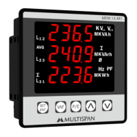
Displays voltage (V) and frequency (Hz) readings for 3-phase systems.

Page 6: Power and Energy

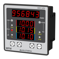
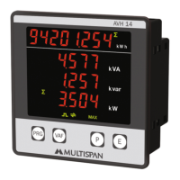
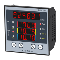
Shows power (KW) and energy (KWH) values for 3-phase systems.

Page 7: Apparent Power

Displays apparent power (KVA) and reactive power (KVAr) for 3-phase systems.

Page 8: Energy and Reactive Power

Shows energy (KWH) and reactive power (KVAr) readings for 3-phase systems.

Page 9: Phase Voltages and Currents

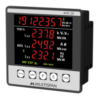
Displays phase voltages (VLN) and phase currents (I) for 3-phase systems.

Page 10: Phase Power Factor

Shows phase power factor (PF) for each phase in 3-phase systems.

Page 11: Load Hours

Displays load hours (Lhrs) and related time parameters.

Page 12: RPM and Load Hours

Shows RPM and load hour readings for operational monitoring.

Page 13: No Load Hours

Displays no load hour readings and related time parameters.

Page 14: KVAh Display

Shows KVAh (apparent energy) readings for 3-phase systems.

Page 15: KVArh Display

Displays KVArh (reactive energy) readings for 3-phase systems.

Mechanical Dimensions and Installation

Panel Cutout and Dimensions

Provides detailed dimensions and panel cutout requirements for unit installation.

Installation Guidelines

Instructions for fitting the unit into the panel, avoiding heat sources, and using terminals.

Safety Precautions

Electrical Shock Warning

Critical warnings about the risk of electric shock and the need to follow safety instructions.

Operational Safety

Guidelines for safe operation, including power supply checks and reading instructions.

Warning and Installation Guidelines

Electrical Safety Warnings

Precautions to prevent electric shock, including keeping power OFF during wiring.

EMI Reduction

Tips for reducing electromagnetic interference using adequate wiring.

Installation Best Practices

Guidelines for installing the unit, avoiding debris, and using accessible circuit breakers.

Maintenance Procedures

Instructions for cleaning the equipment and caution against replacing fusible resistors.

Related product manuals