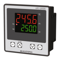
This document describes the UTC-2202G Temperature Controller, a device designed for precise temperature management.
Function Description
The UTC-2202G is a temperature controller that offers various control modes and features for industrial applications. Its primary function is to regulate temperature based on user-defined set points and parameters. The device supports different input types (J, K, PT-100, J.1, K.1, PT.1) and provides multiple control outputs, including PID, ON-OFF, and alarm functions. It also incorporates a "Soak Time" feature, allowing the process to be held at a preset temperature for a specified duration.
The controller can operate in several cases, including:
- Case 1: Heat + Soak + Alarm: For processes requiring heating, a soak period, and alarm notifications.
- Case 2: Heat + Heat: For dual heating applications.
- Case 3: Heat + Cool: For applications requiring both heating and cooling control.
- Case 4: Heat + Alarm: For heating with alarm functionality.
- Case 5: Cool + Cool: For dual cooling applications.
- Case 6: Cool + Alarm: For cooling with alarm functionality.
- Case 7: Alarm + Alarm: For dual alarm functionality.
The device features an Auto-tuning function that automatically calculates and sets optimal Proportional band (Pb), Integral time (It), Derivative time (dt), and cycle time parameters based on the process characteristics. A dedicated LED indicates when Auto-tuning is active. If power is interrupted during auto-tuning, the process will restart upon power restoration.
Important Technical Specifications
Output Specification:
- Relay Output: 2 nos.
- Relay Type: 1 C/O, (NO-C-NC)
- Rating: 10A, 230V AC / 28V DC
- SSR Drive Output: 12V DC, 30mA DC (ON-OFF Condition)
- Relay 1 Parallel to SSR: Yes
Environment Condition:
- Operating Temp.: 0°C to 55°C
- Relative Humidity: Up to 95% RH (non-condensing)
- Protection Level: IP-65 (Front side) As per IS/IEC 60529: 2001
Technical Specification:
- Input Types: J, K, PT-100, J.1, K.1, PT.1
- Resolution: J,K,PT-100 = 1°C; PT.1 = 0.1°C
- Indication Accuracy: ±1% of FSD ± 1°C
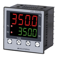
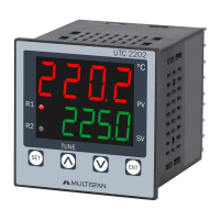
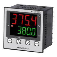
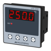
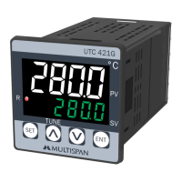
- Display: Upper: 4 digit, 7 segment, 0.70"; Lower: 4 digit, 7 segment, 0.50"
- Keys: SET, INC, DEC, ENT
- Dimensions: 72 (H) x 72 (W) x 85 (D) mm
- Panel Cutout: 68 (H) x 68 (W) mm
- Control Method:
- Heating: 1) PID control with Auto-Tuning, 2) (TP) Time Proportional, 3) ON-OFF control
- Cooling: 1) BL.TP (Blower Time Proportional), 2) ON-OFF control
- Alarm: High / Low / Absolute Low / Inband / Absolute Outband / Outband / End Alarm
- Power Supply: 100 to 270V AC, 50-60Hz
- Power Consumption (VA Rating): Approx. 4VA @ 230V AC MAX
Range for Control Parameters:
- PB (Proportional Band): 0.0 to 999.9°C
- IT (Integral Time): 0 to 9999
- DT (Derivative Time): 0 to 9999
- CT (Cycle Time): 4 to 99 sec
- Offset: -20 to 20°C (for J, K, PT-100) / -20.0 to +20.0°C (for J.1, K.1, PT.1)
- HYS1/HYS2 (Hysteresis): 1 to 100°C (for J, K, PT-100) / 0.1 to 100.0°C (for J.1, K.1, PT.1)
- Soak Time (SKTM): 0 to 999 (Unit As Per Soak Unit Selected)
Usage Features
Key Operation:
- SET: To enter parameter setting.
- A (Up Arrow): To start/stop PID auto tuning, increment parameter value.
- V (Down Arrow): To go to factory setting mode (press 3 sec), decrement parameter value.
- ENT: To reset process after soak time end, save & exit parameter setting.
Parameter Setting:
- Set Point Setting: Allows setting of primary (PV) and secondary (SV) values, and alarm limits (LO, HI).
- Control Parameter Setting: Configures PID parameters (Pb, It, dt, Ct), cooling parameters (C-Pb, C-On, C-Off), and alarm parameters (AL.n, AL.n2).
- Basic Configuration: Sets input type (In.Pt) and control logic cases (Heat + Soak + Alarm, Heat + Heat, etc.).
Soak Time Function:
- Allows holding the process at a preset temperature for a preset time (0 to 999 hours).
- Displays "End" when soak time is completed. Pressing ENT for 3 seconds restarts the process.
- Soak Time Memory (READ): If power fails, "YES" indicates remaining soak time continues on power-up; "nO" indicates soak time restarts.
- Soak Time End (End): If "SAVE" is applied in configuration, the "End" display persists after power failure and resets only by pressing ENT for 3 seconds.
Error Display:
- OPEN: Sensor not connected, over-range condition, or sensor break.
- Sr.E: Sensor connection is reversed.
- Corrective Action: Check sensor and input wiring. If the problem persists, replace the sensor or contact the company.
Status LED Description:
- 1: Soak Time counting indication.
- 2: Control O/P 1.
- 3: Control O/P 2.
- 4: Auto Tuning on indication.
Maintenance Features
Mechanical Installation Guidelines:
- Prepare the panel cutout with specified dimensions.
- Fit the unit into the panel using the provided clamp.
- Ensure the equipment is not near heat sources, caustic vapors, oils, steam, or other unwanted byproducts.
- Use specified size crimp terminals (M3.5 screws) for wiring the terminal block, tightening to 1.2 N.m.
- Do not connect anything to unused terminals.
Maintenance:
- Regularly clean the equipment to prevent blockage of ventilating parts.
- Clean with a soft cloth; do not use isopropyl alcohol or other cleaning agents.
- Fusible resistor must not be replaced by the operator.
Safety Precautions:
- Always follow safety codifications and instructions in the manual.
- Improper handling may impair the protection provided by the equipment.
- Read instructions before installation and operation.
- WARNING: Risk of electric shock.
- Power supply must be OFF during wiring.
- Do not touch terminals when power is supplied.
- Use adequate rated and twisted wires for reduced electromagnetic interference.
- Cable for power connection must have a cross-section of 1mm or greater with insulation capacity of at least 1.5kV.
- Use standard power supply cable for better anti-noise effect.
Installation Guidelines:
- The equipment is built-in type and typically becomes part of a main control panel, making terminals inaccessible to the end user after installation.
- Prevent metal pieces, wire clippings, or fine metallic fillings from entering the product to avoid safety hazards.
- Install a circuit breaker or mains switch between the power source and supply terminal for easy ON/OFF control, located in an accessible place.
- Use and store the instrument within specified ambient temperature and humidity ranges.