Do you have a question about the MULTISPAN UTC-4202G and is the answer not in the manual?
| Output | Relay, SSR, 4-20 mA |
|---|---|
| Control Mode | PID, ON/OFF |
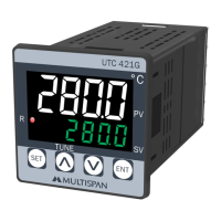
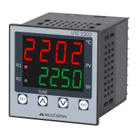
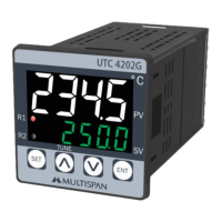
| Display | Dual 4-digit LED |
| Power Supply | 100-240 VAC, 50/60 Hz |
| Number of Outputs | 2 |
| Input Type | Thermocouple, RTD |
| Accuracy | ±0.25% of full scale |
Details input types, ranges, and output specifications for relays and SSR.
Information on display, keys, control methods, and power supply.
Physical dimensions, panel cutout, and environmental operating conditions.
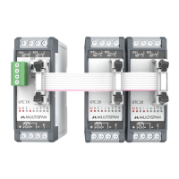
Diagrams illustrating sensor input and output terminal connections.
Explains the meaning of different status LEDs on the unit.
Details key functions in operator and parameter setting modes.
Important safety guidelines for handling and operation.
Warnings and procedures to prevent electric shock during wiring.
Advice on cable selection, wiring, and reducing interference.
Instructions for panel mounting, preventing contamination, and circuit breakers.
Notes on panel cutout, fitting, terminal torque, and unused terminals.
Procedures for cleaning and component replacement warnings.
Instructions for entering and applying factory default values.
List and explanation of parameters related to control functions.
Parameters for setting alarms, setpoints, and limits.
Parameters related to timing, modes, and basic configuration.
Specifies the valid range for control parameters based on input type.
How to use the soak feature to hold process at a preset temperature.
Display indications and restart options upon soak time completion.
How soak time counting is handled during power failures.
Lists common error codes and their corresponding meanings.
Provides steps to resolve sensor connection or range errors.
Diagram showing the sequence for setting parameters like setpoints and limits.
Flowchart for configuring PID, TP, and other control parameters.
Sequence for setting basic configuration options including control cases.
Configuration details for the Heat, Soak, and Alarm control case.
Configuration details for the Heat + Heat control case.
Configuration details for the Heat + Cool control case.
Configuration details for the Heat + Alarm control case.
Configuration details for the Cool + Cool control case.
Configuration details for the Cool + Alarm control case.
Configuration details for the Alarm + Alarm control case.
Illustrates ON-OFF control behavior for heating and cooling.
Explanation of the auto-tuning process and tuning LED indication.