17
HYDRAULIC
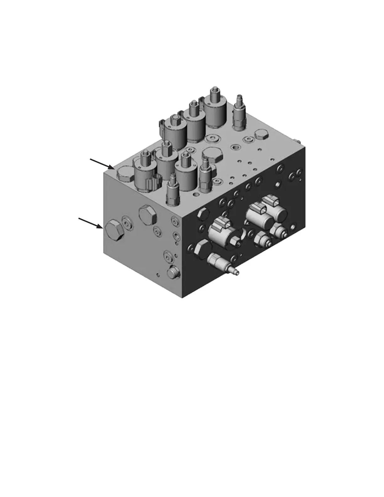
CONFIGURING SYSTEM FROM SA TELESCOPIC TO DA HOIST
Instructions:
1. Locate the CP2 cavity and remove (Hydraforce P/N: CP16-20N)
2. Locate the CP3 cavity, and reinstall the CP16-20N cartridge removed in step 1.
3. Install an SP16-20 into the CP2 cavity (SP16-20M-0-N-12ER)
4. Verify that the conguration le has been set for a “SA telescopic hoist cylinder”
5. Plug the appropriate electrical output into the newly installed SP16-20 (Wire Color Orange)*
The additional electrical hoist output will be a part of the standard wire harness even if unused. We will coil this
additional output if unused.
CP2
CP3