Do you have a question about the Munters HC-150 and is the answer not in the manual?
Explains how the HC-150 removes moisture using the HoneyCombe® wheel.
Provides a simplified explanation of the HC-150's operating principle and key components.
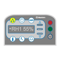
Details the four indicators and controls on the unit's control panel.
Describes sensors and circuits that protect the machine and operator from potential issues.
Explains the meaning of DANGER, WARNING, and CAUTION hazard messages.
Emphasizes risks associated with high voltage and the need for qualified electricians.
Covers warnings about outdoor installation and potential water damage.
Alerts users to the dangers of fast-spinning blowers and the need for guards.
Steps for inspecting the unit for damage and checking components upon arrival.
Specifies required clearances and provides diagrams for unit placement.
Details on connecting ductwork, installing dampers, and insulation requirements.
Covers safe electrical hookup, including disconnect switches and grounding.
Instructions for wiring and mounting a remote humidistat for automatic control.
Guidance on setting process and reactivation air dampers for optimal airflow.
Step-by-step guide for safely replacing fusible links in the unit.
Instructions for cleaning or replacing the unit's two air filters.
How to check the wheel's rotation, cleanliness, and signs of wear.
Procedure to inspect upper and lower air seals for smoothness and wear.
Method for checking the reactivation air outlet temperature against specifications.
General advice on diagnosing problems and preparing for troubleshooting.
Steps to resolve issues when the running light is off in auto mode.
Troubleshooting steps for when the fault light is on during operation.
Diagnosing and fixing causes for insufficient reactivation air temperature.
Addressing factors that lead to poor dehumidification output.
Troubleshooting the drive system when the wheel is stopped but the unit is on.
Procedure to check heating elements for resistance and fusible link integrity.
Guidance on checking the thermistor sensor for the power controller.
Steps to verify the humidistat's operation and electrical connections.
Detailed inspection and maintenance of the drive motor, wheel, and seals.
List of recommended spare parts for the HC-150I model.
| Brand | Munters |
|---|---|
| Model | HC-150 |
| Category | Dehumidifier |
| Language | English |