1–3
figure — the HoneyCombe
®
wheel, process air stream and reactivation air stream. We
have also added a number of other parts:
• Two sets of seals to separate the two streams of air (damp process air and the
heated reactivation air)
• Blower, damper and filter for the process air
• Blower and filter for the reactivation air
• Temperature sensors
• Electric heating elements for the reactivation air
Figures 1–3 and 1–4 show some additional parts on the HC-150 unit. The Honey-
Combe
®
wheel is turned by a small drive motor and a toothed belt. A spring-type
tensioner automatically adjusts the belt tension.
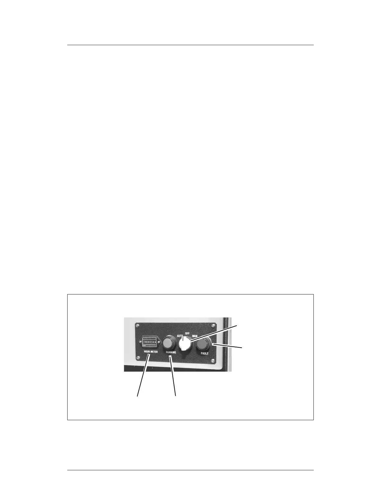
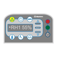
1.3 CONTROLS AND INDICATORS
The unit has four indicators and controls on the control panel:
Auto/Off/Manual switch:
Auto position (amber) This indicator is on whenever the HC-150 is operating in
the automatic mode. The unit is switched on and off by a
remote humidistat.
Off position (amber) This indicator is on when the AC power to the unit is on,
and it is not running (not set to Auto or Manual). (On shut-
down, the heating elements will switch off. The process
FIGURE 1–3
CONTROLS AND INDICATORS
Fault light
Running lightTime meter
Auto/Off/Manual
switch