Section 78 00-02-0732
2016-02-26 - 1 -
Hardware Installation
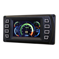
The following instructions will guide you through installing the PV450 display.
Inspecting Package Contents
Before attempting to install the product, it is recommended that you ensure all parts are
accounted for and inspect each item for damage (which sometimes occurs during shipping).
The items included in the box are:
Installation kit – P/N 78-00-0782 includes:
• 4 ea. machine screws and flat washers
• 4 Nylock nuts
• 1 small bag
Dash-Mounted Installation
Tools needed.
• Drill with 5/32” size bit
• Jig Saw or tool that cleanly cuts through dash material.
• Wrench or socket
Preparing the Dash
Determine the location of the PowerView 450 in the dash. Use the Installation Template
(included at the end of the manual) as a guideline to cut a hole in the dash to the specified
dimensions. Drill holes where indicated on the template for the mounting screws.
NOTE: When using the paper template from the manual, please be aware that if
you downloaded this document from the FW Murphy website, the pdf file may not
automatically print to scale. When submitting the file for print, you will need to
select “None” for Page Scaling. Check the accuracy of the printed template by
verifying the measurements labeled on the template are correct.
If this manual was supplied with your product, the template will be correct.
 Loading...