2202L5JE-DA-C5-N_2015.05.
5 Maintenance and Inspection
Compound 2-stage Screw Compressor 5.5 Reassembly
1612LSC Speed Increaser Type
5-64
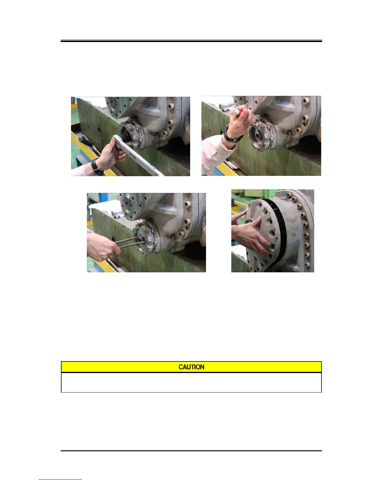
f) Insert a new lock washer [70] and the lock nut [69] into the unloader push rod, tighten the lock nut
and bend the lock washer tooth into the notch of the lock nut to prevent loosening. The tightening
torque for this lock nut is 80 N·m.
g) After securing the unloader piston, screw eyebolts into the unloader piston, and move the piston 2
to 3 times to check it’s motion.
Tightening Lock Nut to secure Unloader Piston Bending the Lock Washer Tooth
Lastly, Pulling Piston to Front Attaching Speed Increaser
Gear Casing Cover
h)
The speed increaser gear casing cover [171] has a lubrication hole for the thrust bearing and
mechanical seal for the speed increaser gear spindle and the hole has the oil flow control throttle
[196-1] screwed inside. Install the speed increaser gear casing cover after checking that this hole is
not clogged.
When attaching the cover, fit its convex portion into the concave portion of the thrust bearing gland
in the speed increaser gear casing and then fasten the cover with the hexagon socket head cap
screws [195] to the specified torque.
Do not fail to install the speed increaser gear casing cover gasket [172].
Speed increaser gear casing cover gasket [172] is not symmetrical because it has
an oil hole on one side. Take care not to attach the gasket incorrectly.
 Loading...


