2202L5JE-DA-C5-N_2015.05.
5 Maintenance and Inspection
Compound 2-stage Screw Compressor 5.4 Disassembly and Inspection
1612LSC Speed Increaser Type
5-18
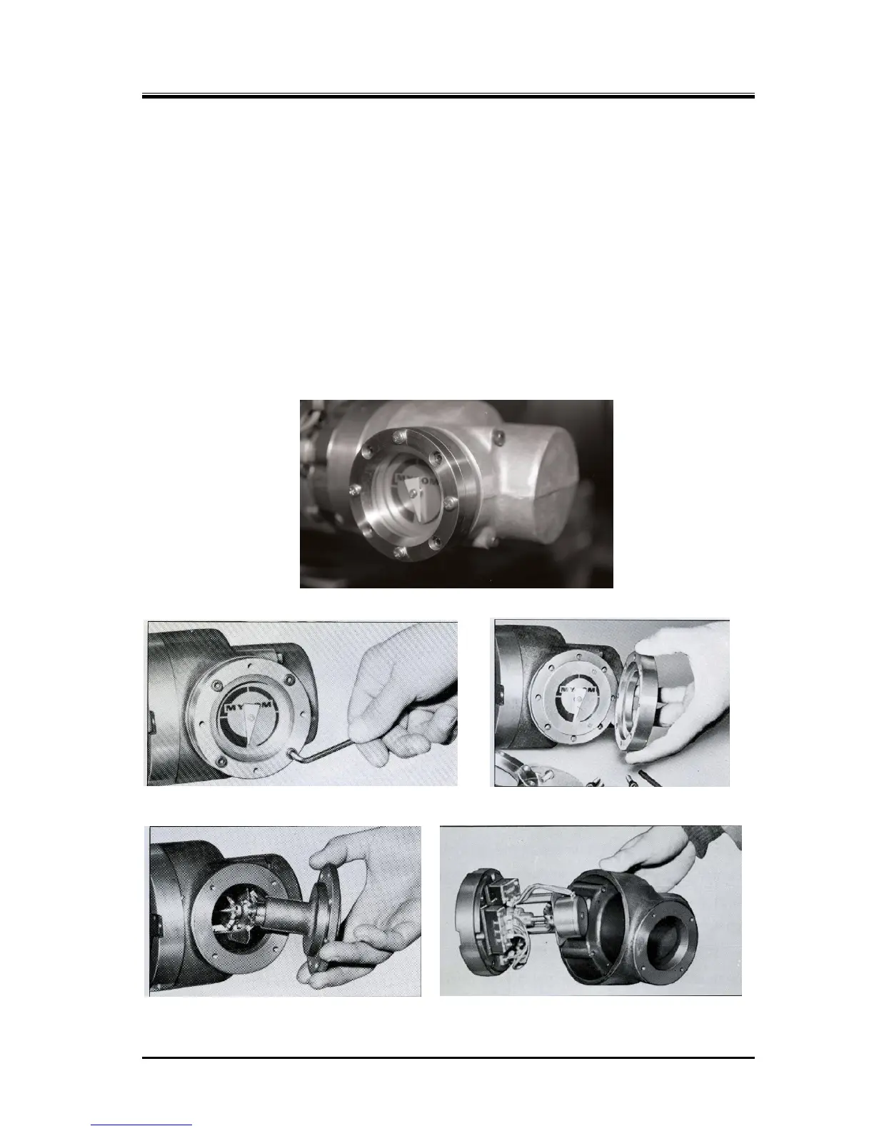
5.4.2.1 Disassembly
When removing wiring only
Remove the indicator cover before pulling out the unloader indicator wiring because the indicator
has a terminal board for wiring. Perform the work as described below and after removing the wiring
reattach the cover for protection.
a) Loosen the
hexagon socket head cap screws [212] holding the indicator glass. Do not
mistakenly loosen the phillips screws [210] on the same surface. Remove the indicator shaft
assembly parts [141], [202 – 207], [210], and [211].
b) Remove hexagon socket head cap screws [147A] [147B] (two each) that fasten the indicator
cover [146]. Then the cover gets removable.
c) Since there is a terminal block [132], remove wiring after removing the surface plastic sheet and
loosening the screws.
Unloader Indicator Assembly Part
Removing Indicator Glass and Gland Removing Indicator Glass and Gland
Removing Indicator Shaft Assembly Removing Indicator Cover
 Loading...


