2202L5JE-DA-C5-N_2015.05.
5 Maintenance and Inspection
Compound 2-stage Screw Compressor 5.4 Disassembly and Inspection
1612LSC Speed Increaser Type
5-32
5.4.12 Low-stage Suction Cover and Side Bearings
Similarly to the case of the high-stage,
remove the low-stage suction cover before
disassembling the low-stage thrust bearing
block in order to prevent the rotor dropping at
the time of removing the suction cover.
Also in the same way of the high-stage, the
lock nut fastening the thrust bearing should
be loosened beforehand.
In the case of 1612LSC speed increaser type,
the thrust bearing inner race on the low-stage
M rotor is fastened together with the speed
increaser driven gear [179] by the lock nut
[39-1A]. First, pull out this driven gear to
loosening the lock nut.
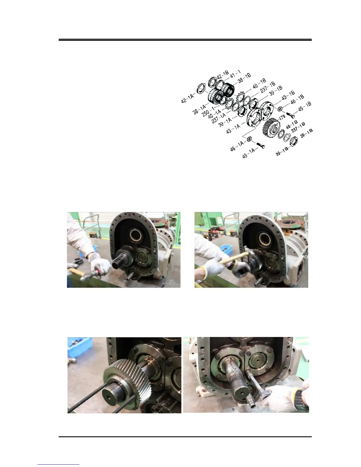
5.4.12.1 Disassembly
a) As shown in the following picture to the left, unbend the rotation stopper tooth of the lock washer
[40-1B], loosen the lock nut [39-1B] (following picture to the right) which is fastening the speed
increaser driven gear [179]. Then, remove the lock nut, torsional slip washer [237-1B] and lock
washer [40-1B].
b) As shown in the following picture to the left, pull out the speed increaser driven gear, and remove
the shaft key [180] for rotation stopper of the driven gear.
c) Remove the hexagon head bolts [45-1] that is fastening the thrust bearing gland [43-1] together
with the spring washer [46-1] (following picture to the right).
d) Remove the thrust bearing gland.
Figure 5-9 Low-stage Thrust Bearing Block
 Loading...


