2202L5JE-DA-C5-N_2015.05.
5 Maintenance and Inspection
Compound 2-stage Screw Compressor 5.5 Reassembly
1612LSC Speed Increaser Type
5-46
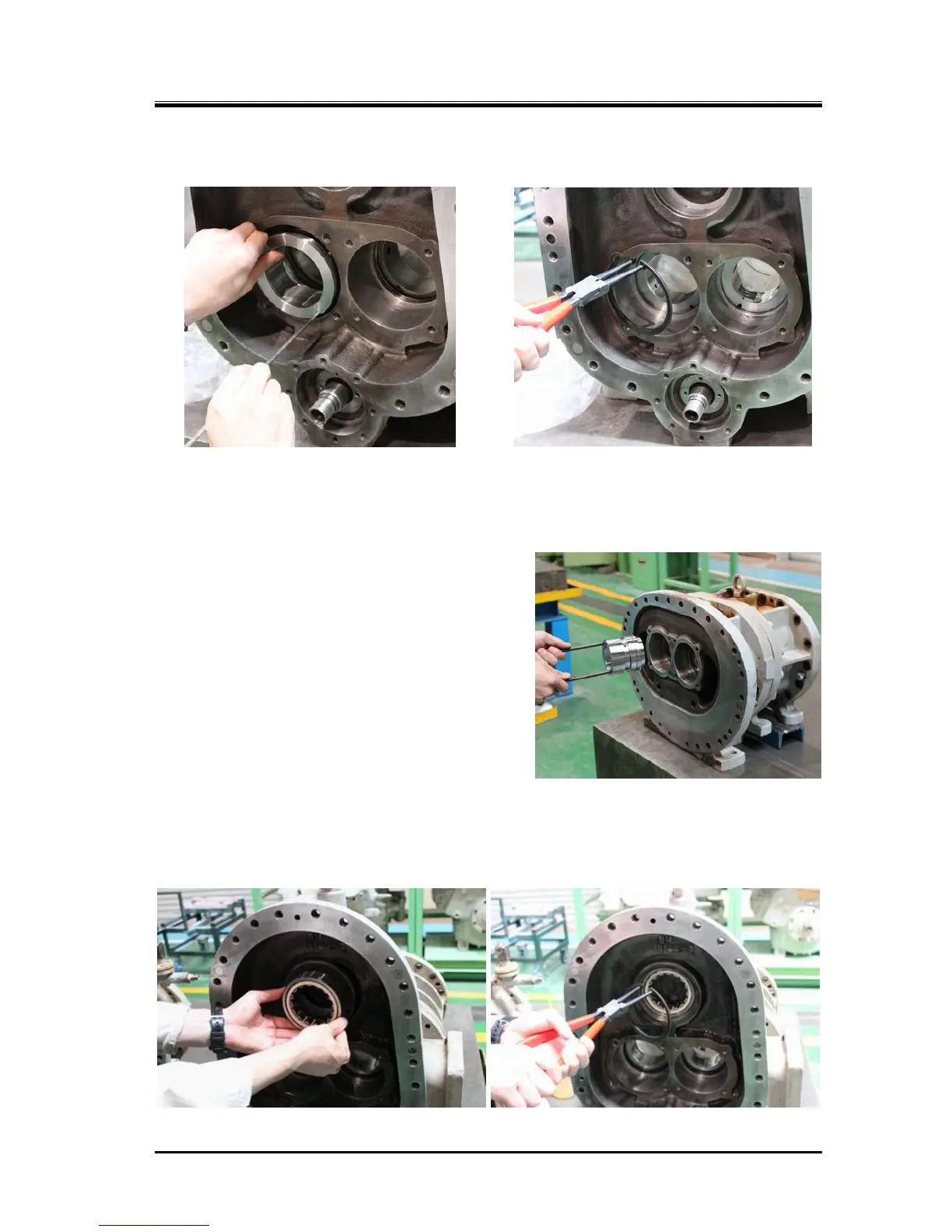
5.5.3 Bearing Head and Main Bearings
a)
The main bearing [27] is dimensioned in such a way that it is lightly press fit to the bearing head [11].
Position the notch of the main bearing so that it is aligned with the spring pin [14] in the bearing
head (in the case of low-stage work, using a fixture such as a guide rod is helpful as shown in the
above picture to the left), then, using a pad, lightly tap in the notch.
High-stage main bearings are pushed into bearing
head using M8 eyebolts as shown in the right picture.
If the position is not aligned, pull out the main bearing
and install it in again.
b)
After attaching main bearings, secure them by
attaching internal snap rings (above picture to the
right).
c)
Low-stage bearing head [11-1] has two lubrication
holes for the speed increaser gear and the speed
increaser gear spindle. These lubrication holes are
screwed in the oil flow control throttles [196-2],
Make sure to check that there are not clogged in
the lubrication holes and throttles.
d)
Install the outer race of the roller bearing [185] for the speed increaser gear spindle [188] into the
low-stage bearing head (following picture to the left) by securing with the internal snap ring [186]
(following picture to the right).
* : This assembly work may be performed as part of the reassembling procedure of the speed
increaser gear casing.
 Loading...


