2202L5JE-DA-C5-N_2015.05.
5 Maintenance and Inspection
Compound 2-stage Screw Compressor 5.4 Disassembly and Inspection
1612LSC Speed Increaser Type
5-21
5.4.4 Unloader Piston and Unloader Cylinder
5.4.4.1 Disassembly
a) Screw two M8 eyebolts into the unloader piston [64],
and pull out it to the no-load position (utmost front
position).
b) Unbend the rotation stopper tooth of the lock washer
[70], loosen and remove the lock nut [69].
c) Now, you can remove the unloader piston.
d) The unloader cylinder [60] is attached to the
low-stage bearing head [11-1] along with the speed
increaser gear casing [169] by eight long bolts [61].
Remove [61] and then pull out the unloader cylinder.
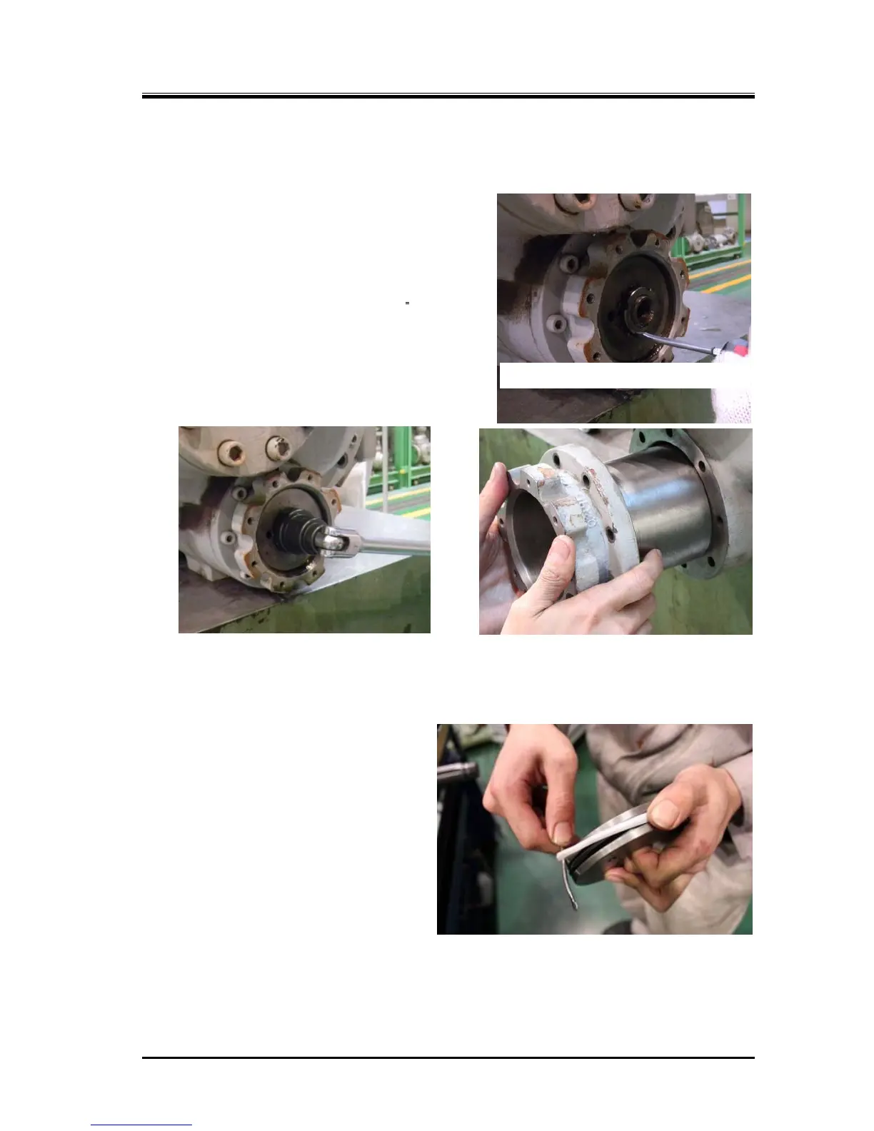
Loosening Lock Nut Removing Unloader Cylinder
5.4.4.2 Inspection
a) Remove and inspect the O-ring [65]
attached to outside the unloader piston
and the cap seal [66], testing the O-ring
for elasticity and deformation. Replacing
the O-ring is recommended after more
than two years of use.
b) Since the unloader cylinder often has
damage or oil refuse stuck to the inner
surface, clean thoroughly and use fine
sandpaper to smoothen it.
Removing the Cap Seal
Unbending Lock Washer Tooth
 Loading...


