2202L5JE-DA-C5-N_2015.05.
7 Related Documents
Compound 2-stage Screw Compressor 7.3 Tightening Torques for Bolts and Nuts
1612LSC Speed Increaser Type
7-10
Locknut
P/N Tightening point
Tightening torque
N·m
Qty. Size
Regular
use
Maxi-
mum
39-1A Thrust bearing (1) M 656 820 1 AN14
39-1B Thrust bearing (1) F
Speed increaser driven gear
408 510 2 AN12
39-2 Thrust bearing (2) 206 258 2 AN09
69 Unloader piston 80 — 1 AN05
71 Unloader slide valve 49 61 1 AN06
160 Intermediate gear coupling, drive hub 90 113 1 AN08
193 Thrust bearing, speed increaser gear 522 653 1 AN13
269 Speed increaser drive gear 1186 1483 1 AN17
Note: When tightening a lock nut, if it is difficult to use a torque wrench, manage the tightening torque
of the lock nut controlling the tightening angle range as explained below.
Tightening Angle Range of Lock Nuts for Rotors
a) After tightening the lock nut by hand, further tighten the lock nut by using a lock nut wrench until the
rotor starts to turn. Take care not to over-tighten.
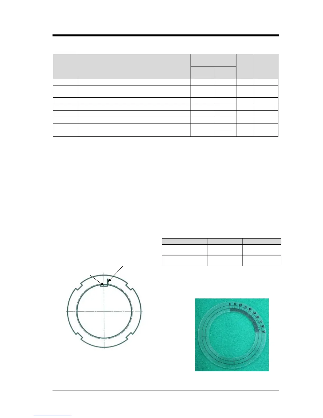
b) Put a mark on the lock nut at the right side edge of the rotor groove where the stopper tongue of the
lock washer fits in, as shown in Figure 7-9.
c) From this marking position, tighten the lock nut in such a way that rotation can be stopped within the
tightening angle range shown in Table 7-3 (2016**C【39-1】,【39-2】and【160】: 30° to 40°(first time
tightening), 20° to 30°(second time tightening). When measuring the angle, use an angle gauge
which is set to the diameter of rotor shaft.
Table 7-3 Tightening Angles Specified
for Lock Nuts of Rotor
* When tightening lock nut, tightening start position
differs between the first time tightening and the
tightening for the second time or after. Therefore,
angle ranges are specified also for the second
time tightening.
Figure 7-11 Position where mark is put
Angle Gauge (example)
Model Angle range
First time
tightening
125 to 250 30° to 40°
Second time
tightening
125 to 250 20° to 30°
Marking
Rotor groove (slot)
where stopper tongue of
the lock washer fits
 Loading...


