Home
mycom
Air Compressor
1612LSC series
mycom 1612LSC series User Manual
5
of 1
of 1 rating
145 pages
Give review
Manual
Specs
To Next Page
To Next Page
To Previous Page
To Previous Page
Loading...
2202L5JE-DA-C5-N_20
15.05.
3 Installation
Compound 2stage Screw Compresso
r
3.2 Installation Works
1612LSC Speed Increaser T
ype
3-3
Outer Dimensions, Mass and Lif
ting Position
1612LSC speed increaser type comm
on
M
a
s
s
(
k
g
)
5
6
0
Length (mm)
1372
Figure 3-1
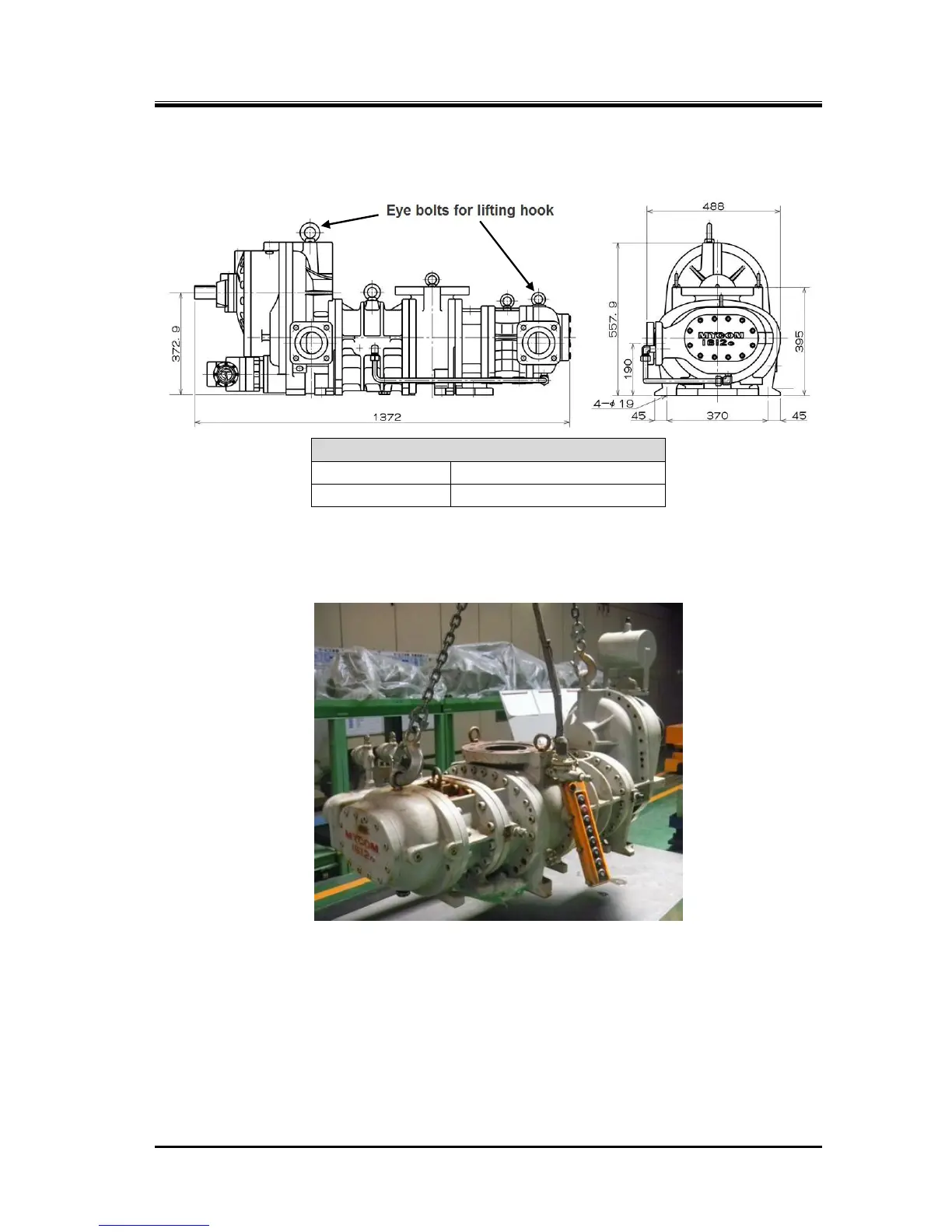
Outer Dimensions, Mass and Lifting Position of Compressor
Lif
ted
View
30
32
Table of Contents
Default Chapter
1
Instruction Manual
1
Important Information
4
About this Manual
5
Table of Contents
6
Safety
11
Strict Requirements and Prohibitions
11
Strict Requirements (Do's)
11
Do's on Lockout/Tagout after Shutting off the Power
11
Do's on Maintenance
11
Do's on Operation
11
Do's about Handling Emergency Situations
12
Do's about Personal Protective Gear
12
Do's about the Handling of Hazardous and Toxic Substances
12
Do's about Waste Oil, Fluid, and Materials
12
Other Do's
12
Prohibitions (Don'ts)
13
Warnings
13
Residual Risks
14
Safety Devices
16
Emergency Stop Button
16
2.1 Overview of the Compound 2-Stage Screw Compressor
17
Compressor Protection Devices
17
Model Designation of the Compressor
19
Compressor Specifications
20
Standard Specifications
20
Operation Limits
21
Outer Dimensions
22
Structure of Compressor
23
Mechanisms
24
Basics of the Screw Compressor
24
Suction Process
24
About Volume Ratio (VI)
25
Compression Process
25
Discharge Process
25
Bearings and Balance Piston
27
Capacity Control Mechanism
27
Shaft Seal
27
Gas and Oil Flow
28
Installation
29
General Precautions for Installation
29
Installation Works
29
Storage
29
Transportation
29
Unpacking
29
Preparation for Installation
32
Installation
33
Shaft Alignment between Compressor and Driving Machine
33
Equipment and Devices for Protection of the Compressor
34
Piping Connection
34
Additional Charge of Lubricating Oil
35
Airtightness Test
35
Charge of Refrigerant
35
Check after Installation
35
Initial Charge of Lubricating Oil
35
Lubricating Oil Charge
35
Compressor and Package Unit Operation
36
Lubricating Oil (Refrigerant Oil)
36
Precautions for Selecting the Lubricating Oil
36
Recommended Lubricating Oils
36
Recommended Lubricating Oils for Ammonia Refrigerant
36
Oils for Systems Using Hydrofluorocarbon (HFC) Refrigerants
37
Change of Lubricating Oil Brand
38
Precautions for Handling Lubricating Oil
39
Precautions for Handling Polyalkylene Glycol (PAG)
39
Precautions for Handling Polyolester (POE) Oil
39
Lubricating Oil Management Criteria
40
After Starting the Initial Operation
41
During Normal Operation
41
Lubricating Oil Replacement Timing
41
Compound 2-Stage Screw Compressor 1612LSC Speed Increaser Type
42
Precautions for Operation
42
Prevention of Liquid Flow-Back
42
Purging of Non-Condensable Gases
42
When Stopping the Compressor for a Long Time
43
Maintenance and Inspection Precautions for Maintenance and Inspection
44
5.1 Precautions for Maintenance and Inspection
46
Maintenance and Inspection List
46
Daily Management
46
Periodic Inspection
48
Guidelines for the Timing of Compressor Overhaul
49
Compressor Disassembly Preparation
50
Disassembly Tools and Workplace
50
Replacement Parts
50
Refrigerant Gas Recovery
53
Removing Parts Connected to the Unit
54
Compressor Removing and Lifting
55
Removing Oil from Inside the Compressor
55
Disassembly and Inspection
56
Disassembly
58
Shaft Seal Block
58
Inspection
59
Unloader Indicator
60
Disassembly
61
Inspection
62
Disassembly
63
Inspection
63
Unloader Cover
63
Disassembly
64
Inspection
64
Unloader Piston and Unloader Cylinder
64
Disassembly
65
Speed Increaser Gear Casing Cover
65
Disassembly
66
Speed Increaser Gear Casing Block
66
Inspection
69
Disassembly
70
Separating High-Stage and Low-Stage
70
Disassembly
71
Gear Coupling
71
Inspection
71
Balance Piston
72
Balance Piston Cover
72
Compound 2-Stage Screw Compressor 1612LSC Speed Increaser Type
73
Inspection
73
High-Stage Suction Cover and Side Bearings
74
Disassembly
74
Inspection
74
Low-Stage Suction Cover and Side Bearings
75
Disassembly
75
Inspection
76
Thrust Bearings Block
77
Disassembly of High-Stage Thrust Bearing Block
77
Disassembly of Low-Stage Thrust Bearing Block
78
Inspection (High-Stage/Low-Stage)
79
High-Stage Rotors and Main Rotor Casing
80
Disassembly
80
Inspection
80
Low-Stage Rotors and Main Rotor Casing
81
High-Stage Bearing Head and Main Bearings
82
Disassembly
82
Inspection
82
Low-Stage Bearing Head and Main Bearings
83
Disassembly
83
Inspection
83
Low-Stage Unloader Slide Valve and Guide Block
84
Disassembly
84
Inspection
84
Reassembly
85
Low-Stage Unloader Slide Valve and Guide Block
87
Bearing Head and Rotor Casing
88
Bearing Head and Main Bearings
89
Rotor Assembly
90
Suction Cover and Side Bearings
91
Thrust Bearing Block
93
End Clearance Measurement
95
End Clearance Adjustment Method
97
Tightening after End Clearance Adjustment
97
Combining High-Stage and Low-Stage Blocks
99
Balance Piston Cover
100
Speed Increaser Gear Block
101
Installation of Speed Increaser Gear Casing to Low-Stage Bearing Head
104
Unloader Cylinder and Unloader Piston
106
Unloader Cover
108
Shaft Seal Block
109
Unloader Indicator
112
Micro-Switch
113
Potentiometer
113
Assembly and Adjustment
114
Troubleshooting
115
01: Compressor Does Not Start up
115
02: Compressor Stops Immediately after Startup
115
03: Unusually Low Pressure (Decrease of Suction Pressure)
116
04: Low Oil Pressure (Low Lubricating Oil Supply Pressure)
116
05: Intermediate Pressure Is Unusually High
117
06: Unusually High Pressure (Abnormal Discharge Pressure)
118
07: Discharge Temperature Is Abnormally High
119
08: Leak from Mechanical Seal
120
09: Squeaking of Mechanical Seal
121
10: Capacity Control Position Is Indicated Incorrectly
121
11: Capacity Control Malfunction
122
12: Compressor Generates Abnormal Vibration And/Or Sound
123
Related Documents
126
Development Views, Assembly Sectional Views
126
Figure 7-3 Assembly Sectional View (Vertical)
128
Figure 7-4 Assembly Sectional View (Horizontal)
129
Parts Configuration Table
130
Tightening Torques for Bolts and Nuts
134
O-Rings for Use
136
List of O-Rings for Use
136
List of O-Ring Materials for Screw Compressor
136
Contact Information
138
Sales Offices in Japan
138
Manufacturing Bases in Japan
138
Global Network
139
North America
139
EUROPE and AFRICA
139
Asia Pacific
140
Latin America
142
5
Based on 1 rating
Ask a question
Give review
Questions and Answers:
Need help?
Do you have a question about the mycom 1612LSC series and is the answer not in the manual?
Ask a question
mycom 1612LSC series Specifications
General
Brand
mycom
Model
1612LSC series
Category
Air Compressor
Language
English
Related product manuals
mycom 160VLD
161 pages
mycom 160VMD
161 pages
mycom 160VSD
161 pages
mycom 170JL-V
209 pages
mycom 320MUD
179 pages
mycom 200VSD
161 pages
mycom 200SUD
179 pages
mycom 200MUD
179 pages
mycom 220JL-V
209 pages
mycom 2016LMC
153 pages
mycom SCV Series
161 pages
mycom 2016 C Series
153 pages