2202L5JE-DA-C5-N_2015.05.
5 Maintenance and Inspection
Compound 2-stage Screw Compressor 5.4 Disassembly and Inspection
1612LSC Speed Increaser Type
5-24
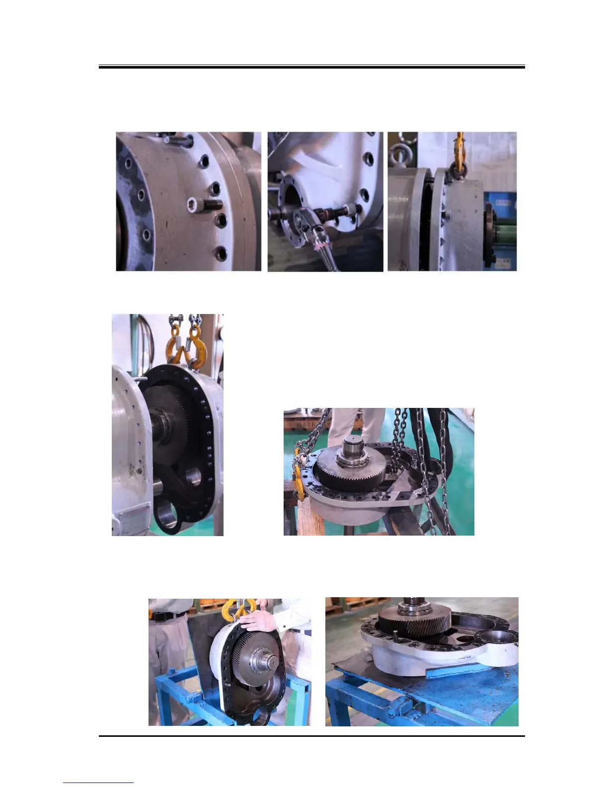
e)
Screw the previously removed three bolts [18-1] into the jacking threaded holes in the flange of the
speed increaser gear casing, and screw them alternately and evenly to separate the flange from
the speed increaser gear casing (picture below).
f) After disengaging alignment pins, pull out the casing with parallel direction to the speed increaser
gear spindle shaft (following picture to the left).
When there is no need to replace the speed increaser drive gear [174]
and/or speed increaser gear spindle [188] because no abnormalities
are observed in them, it is not necessary to remove the speed
increaser drive gear from the speed increaser gear spindle.
In such a case, start next disassembly work from removing the inner
race of roller bearing [185] described in step k) on next page.
Following steps g) to j) are the procedures for replacing the speed
increaser drive gear and/or spindle [188].
g)
Place the speed increaser gear assembly on the work stand while facing the drive gear up, i.e. the
thrust bearing toward floor. It is acceptable to use to the work stand as shown in the above picture
to the right. However, if you can prepare the special work stand with the angle changeable surface
as shown in the following picture, you can do more safely work.
 Loading...


