2202L5JE-DA-C5-N_2015.05.
5 Maintenance and Inspection
Compound 2-stage Screw Compressor 5.5 Reassembly
1612LSC Speed Increaser Type
5-55
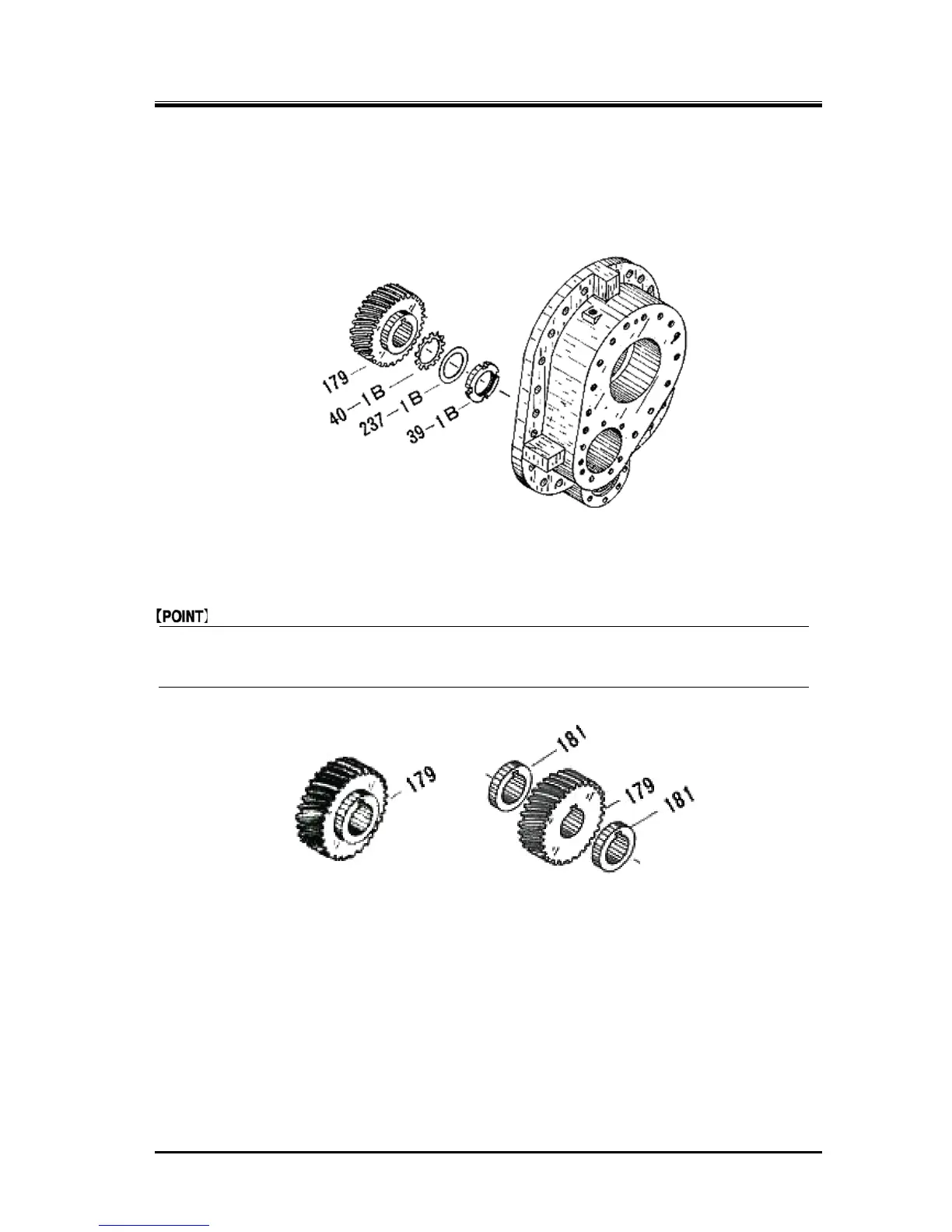
c)
When reassembling the low-stage compressor section of the -53, -54 and -63 models with a speed
increaser gear system, install the speed increaser driven gear [179] on the M rotor shaft by
locking the gear with the key [180]. Secure the gear by fastening the lock nut with the lock washer
and spacer placed in-between. Lock the lock nut by bending a tooth of the lock washer.
Figure 5-18 Speed Increaser Driven Gear
In the -52 and -62 models which are equipped with a speed increaser gear system and driven by
a 4-phase electric motor, the speed increaser driven gear has spacers [181] on both the front and
rear sides (refer to Figure 5-19).
*
For -53, -54 and-63 models For -52 and -63 models
Figure 5-19 Difference in Type of Speed Increaser Driven Gear
 Loading...


