2200LZJE-HO-C6-N_2013.12.
Chapter 5 Maintenance
Compound 2-stage Screw Compressor 2016**C 5.7 Reassembly
5-51
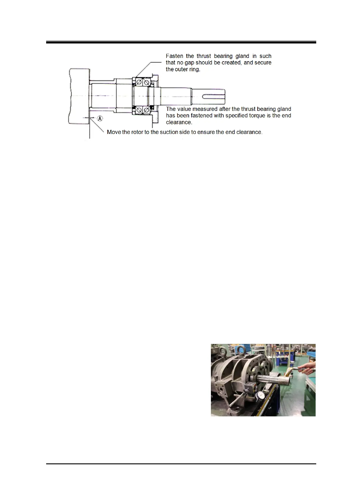
Figure 5-11 End Clearance Adjustment [Ⅱ]
5.7.7.2 Procedure for End Clearance Adjustment
(1) When end clearance is smaller than the specified value
To deal with this, insert shim material (thrust adjustment liner) of required thickness (difference in
thickness from the specified value) between the thrust bearing alignment spacer 【42】 and thrust
bearing inner ring.
* The thrust adjustment liner is not shown in the development view, but available from us. Place an
order together with a model name.
Or using a highly accurate surface grinding machine or asking professional service vendors to
grind, grind the surface of thrust bearing outer race saucer【41】 by the difference from the
specified value. After grinding the flat surface, measure the whole circumference of the saucer by
using a micrometer, and check that the thickness is even.
(2) When end clearance is larger than the specified value
As the end clearance is excessive, remove shim material (thrust adjustment liner) of a thickness
equal to the difference between the measured value and the specified value if the shim material is
used between thrust bearing alignment spacer and thrust bearing inner race.
Or if the shim material is not used between thrust bearing alignment spacer and thrust bearing inner
race, or even if used but insufficient thickness, grind the surface of thrust bearing alignment spacer
【42】 by the difference between the measured value and the specified value or ask professional
vendors to do so.
After grinding the flat surface, measure the whole circumference of the spacer by using a
micrometer, and check that the thickness is even.
(3) Rotor axial runout measurement
When the end clearance has been adjusted to within the
specified range, place a dial gauge on the seal
attachment part of the M rotor shaft. Measure axial runout
by turning the rotor shaft.
The tolerance for axial runout is 0.03 mm or less for all
models.
Runout occurs when the thrust bearing alignment spacer
and saucer are not parallel or when the thrust bearing
mark is not at the correct side.
Small particles of dirt trapped between parts may cause
excessive runout.
If axial runout is over the tolerance, even if the end
clearance is within the specified range, disassemble
and adjust the relative positions of the spacer,alignment spacer and thrust bearing.
This is important because it affects the life of the mechanical seal and its performance.
Photo 092 Measuring Runout of Shaft