2200LZJE-HO-C6-N_2013.12.
Chapter 5 Maintenance
Compound 2-stage Screw Compressor 2016**C 5.7 Reassembly
5-52
5.7.7.3 Tightening after End Clearance Adjustment
a) Bend the lock washer claw to the notch of the lock nut which is tightening the thrust bearing inner
ring, to prevent rotation.
b) Remove the hexagon head bolts that are tightening thrust bearing gland 【43】 one by one. Insert
conical spring washers 【46】 as rotation stoppers, and tighten to the specified torque again.
5.7.8 Bearing Cover
a) Before attaching the bearing cover 【16】, confirm once again that the lock washer claw of the thrust
bearing bended as a rotating stopper and that all the hexagon head bolts for holding the thrust
bearing gland have conical spring washer inserted.
b) Screw the stud bolts into two of the upper holes provided in the flange surface of the bearing head
(1) 【11-1】.
c) Apply oil to the bearing head flange surface and the both surfaces of the bearing cover gasket (1)
【17-1】. Hang the gasket on those stud bolts in such that it is put on the flange surface.
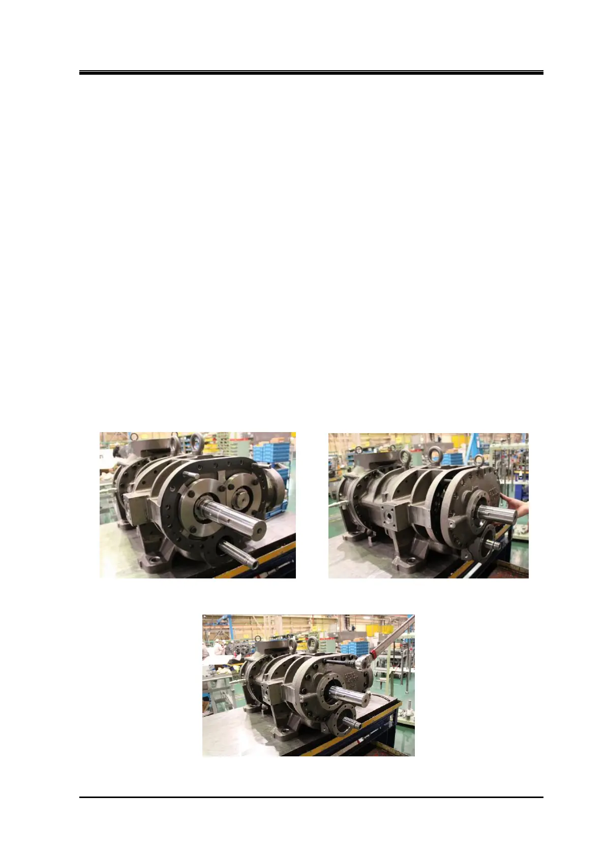
d) Attach O-ring 【197】 to the part where the pushrod goes through bearing cover 【16】.
e) Attach lifting tools to the eye bolt of the bearing cover 【16】. Install the bearing cover taking care not
to let it touch the M rotor shaft or push rod. After it is hung on the stud bolts, the lifting tools can be
removed (Photo 094).
f) Align the alignment pins with the hole. Tap the flanged part alternately with a hammer to attach.
When it becomes possible to screw in bolts, screw in two or three bolts. Evenly narrow the gap until
the mating surfaces come in contact, and then tighten the other bolts.
Photo 093 Stud Bots and Gasket Photo 094 Attaching Bearing Cover
Photo 095 Tightening Bearing Cover