2205B0JE-DA-J-N_2014.05.
7 Related Documents
Screw Compressor J-series 7.1 Development View and Configuration Table of the Parts
7-22
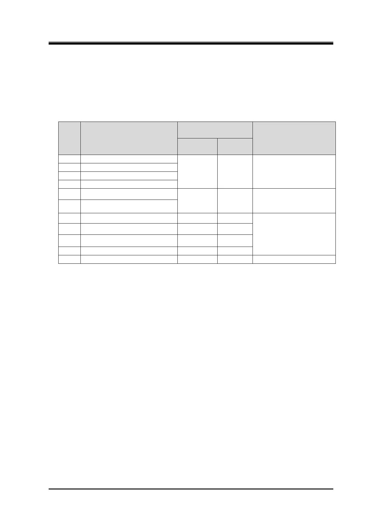
The abolition part and so on
The attendant explanation of the abolition part which is shown by the double strikethrough in table
7-3 is as the following table 7-3b
As for the design modification notification (follow-up), refer to 7.4 "Design Modification Notification
(follow-up)" in this chapter.
Table 7-3b
Part
No.
Part Name
Design Modification
Notification (first)
Remarks
Registration
No.
Issue
Date.
33 Balance piston sleeve
684-037 2012.04.09
Design modification
notification (follow-up)
No.C0956-02
34 Spring pin
35-1 O-ring
36 Balance piston hausing
44-1 Thrust bearing gland spacer, M
684-035 2012.03.29
Design modification
notification (follow-up)
No.C0957-00
44-2 Thrust bearing gland spacer, F
720 Vi position sensor support
These shift to the exclusive
instruction manual as No. 794
Vi position sensor assembly.
721 Potentiometer
722 Hexagon socket head cap screw
724 Vi position sensor box
727 I plug 684-053 2013.10.31