12 of 32
Opus Control Wiring and Programming Installaon Manual www.NabcoEntrances.com
P/N C-00139 Rev 10-20-17
Optional Settings
Parameter Range Default Description
Stop Force Adjustment 0 - 7 3 Determines how the door reacts to a connuous safety signal:
Slow Open, Stop, or Slow Close
Sim Pair Setting Single Door Single
Door
Select type of Door
Normal Sim Pair If selected; before returning to last screen, opon to copy
sengs to other Control is given.
Double Egress The Acvaon signal (only) is shared between doors. All other
signals are independent.
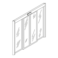
Overlap Sim Pair X Overlap Sim Pair is for an Astragal Applicaon.
X Opus Control connected to door that must open rst must:
3. Have acvaon signals connected to it
4. Be set to “Overlap Sim Pair”
X The delayed control will be set to “Normal Sim Pair”
X Latch Check range is wider than normal seng.
X If selected; before returning to last screen, the opon to
copy sengs to the other Control is given
Output Settings
Parameter Terminal Range Default Description
Output 1 Terminal 7 X Fully Opened Posion
X Fully Closed Posion
X Closing Status
X Opening Status
X Full Opened Posion
X Error State Output
X Recycle happened
X Electric Strike Lock
X Electric Magnec Lock
X Air lock
X Breakout Pass through
X Door Sequencing
X Sensor Monitoring (N.O.)
X Sensor Monitoring (N.C.)
X BEA Bodyguard Output
Full Open X Output doesn’t change state
X Output changes when fully closed
X Output changes when door is closing
X Output changes when door is opening
X Output changes when fully open
X Output changes when error detected
X Output changes when recycle occurs
X Set for electric strike funconality
X Set for Mag lock funconality
X Set for Air lock funconality
X Output changes when breakout occurs
X Provision for door sequencing
X Normally open contacts for Monitoring
X Normally closed contacts for Monitoring
X For BEA Bodyguard
Output 2 Terminal 13 Full Closed
Relay Output 3 Electric Lock
Terminals
— —
Open Delay Timer N/A X 0.1, 0.4, 1.5 sec
X Aer Unlock Input
0.4 X Delay time after activation to allow lock to
unlock before the door starts moving.
X Only functional if Electric Lock is selected
Sequence
Delay Timer
N/A 0-10, 12, 15, 20, 25, 30 0
Amount of Hold Open me aer deacvaon
in seconds
Lock Condition N/A X Every Fully Closed
X One way/Night Only
Every Fully
Closed
Determines when the electric lock engages
Input Settings
Parameter Terminal Range Default
Input 62 Terminal 4 — — Exterior
Activation
No input
All Acvaon Mode Activates in all modes but OFF
Interior Acvaon Activation on interior for One Way mode
Exterior Acvaon Activation on exterior
Beam Sensor Beam input
LE Approach Sensor LE door mounted sensor
Unlock Input Receives unlocked signal from elec Lock
Spring Close Only Turns off power close and hold close