20 of 32
Opus Control Wiring and Programming Installaon Manual www.NabcoEntrances.com
P/N C-00139 Rev 10-20-17
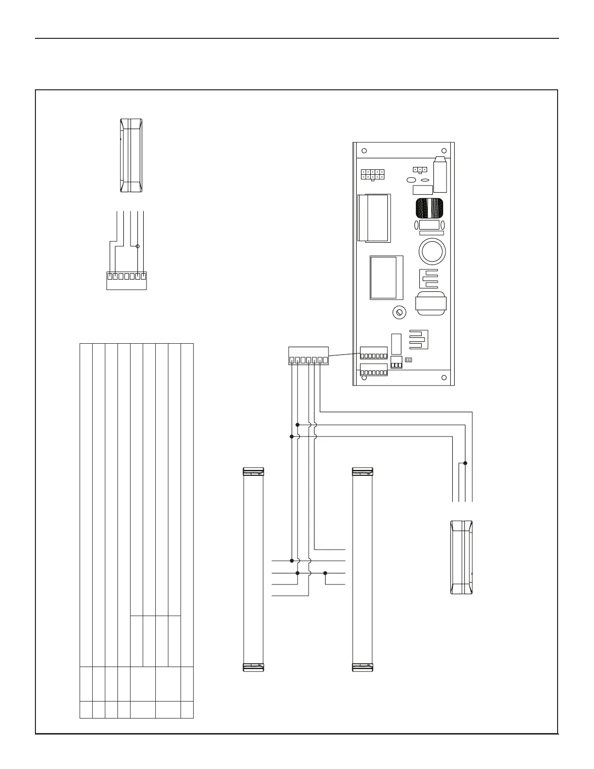
SECTION 11.3: Safety
DN 1331
1 12VDC +12VDC
2GND Common for 12V and Signals
361Interior Ac va on
462Exterior Ac va on/Programmable Input
56BSwing Door Con nuous Safety (door mounted, swing side Safety Sensor)
Slide Door Holding Beam
6SWL Swing Door Safety with Lockout (overhead, swing side safety sensor)
Slide Door Sidelite Sensor
7Out1Programmable Output
1413121110
98
7
6
54
321
7
6
54
321
2
4
COMN.O.
PWR+PWR-
1
Door Mounted
Approach Side Sensor
Door Mounted
Swing Side Sensor
CO .O.
PWR+PWR-
5
6
COM
N.O.
PWR+
PWR-
Overhead
Swing Side Sensor
COM
N.O.
PWR+
PWR-
7
6
54
321
2
1
7
6
MONITOR
For safety sensors equipped with a monitoring function, Te rminal 7
should be connected to the monitor input of the sensor.
Out 1 (terminal 7) must be set to "Sensor Health Check". See
programming instructions for details.
WARNING!
Total Power Consumption Of All Sensors And Powered Activation
Devices Must Not Exceed 750 mA
NM
 Loading...