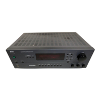
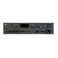
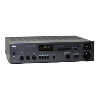
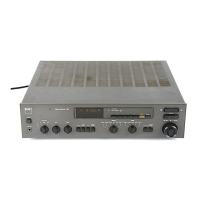
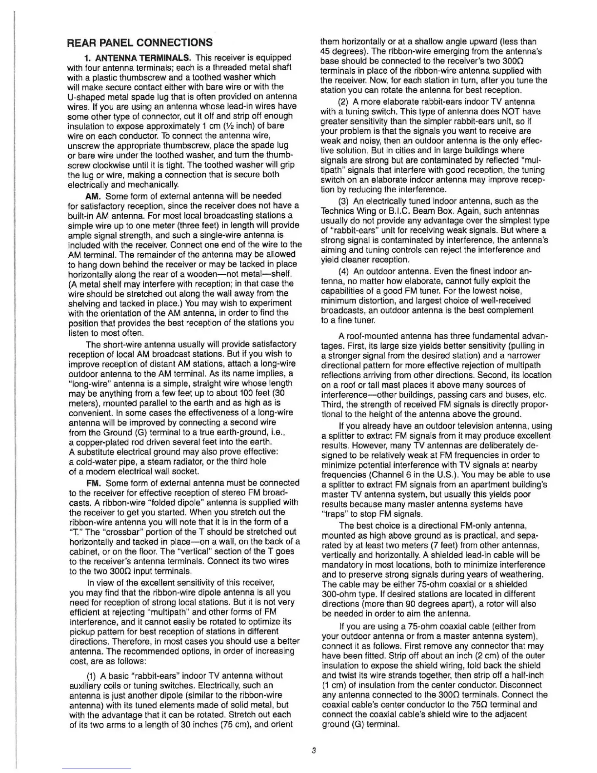
REAR PANEL CONNECTIONS
1.
ANTENNA
TERMINALS. This receiver is equipped
with four antenna terminals; each is a threaded metal shaft
with a plastic thumbscrew and a toothed washer which
will
make
secure contact either with bare wire or with the
U-shaped metal spade
lug that is often provided on antenna
wires.
If you are using an antenna whose lead-in wires have
some other type of connector, cut it off and strip off enough
insulation to expose approximately 1 cm
(V
, inch) of bare
wire
on
each
conductor
.
To
connect
the
antenna
wire,
unscrew the appropriate thumbscrew, place the spade lug
or bare wire under the toothed washer, and turn the thumb-
screw clockwise until it is tight. The toothed washer will grip
the
lug
or
wire, making a connection that is secure both
electrically and mechanically.
AM.
Some form of external antenna will
be
needed
for
satisfactory
reception,
since
the
rece
iver
does
not
have
a
built-in
AM
antenna. For most local broadcasting stations a
simple wire up to one meter (three feet) in length will provide
ample signal strength, and such a single-wire antenna
is
included with the receiver. Connect one end of the wire
to
the
AM terminal. The remainder
of
the antenna
may
be allowed
to hang down behind the receiver
or
may
be tacked in place
horizontally along the rear of a
wooden-not
metal-shelf.
(A
metal shelf
may
interfere with reception;
in
that case the
wire should be stretched out along the
wall away from the
shelving and tacked in place
.)
You
may wish to experiment
with the orientation
of
the AM antenna, in order to find the
pOSition that provides the best reception
of
the stations you
listen to most often.
The
short-wire antenna usually will provide satisfactory
reception
of
local AM broadcast stations. But if you wish to
improve reception
of
distant AM stations, attach a long-wire
outdoor antenna to the AM terminal. As its name implies, a
"long-wire" antenna is a simple, straight wire whose leng
th
may
be anything from a few feet up
to
about 100 feet (30
meters), mounted parallel
to
the earth and as high as is
convenient.
In
some
cases
the
effectiveness
of
a
long
·wire
antenna will be improved by connecting a second wire
from the Ground (G) terminal to a true earth-ground, i.e.,
a copper-plated rod driven several feet into the earth.
A substitute electrical ground
may
also prove effective:
a cold-water pipe, a steam radiator, or the third hole
of a modern electrical
wall socket.
FM.
Some
form of external antenna must be connected
to the receiver for effective reception of stereo FM
broad-
casts. A ribbon-wire "folded dipole" antenna is supplied with
the receiver to
get
you started. When you stretch out the
ribbon·wire antenna you will note that it is in the form
of
a
"T."
The
"crossbar" portion of the T should be stretched out
horizontally and tacked in
place-on
a wall, on the back
of
a
cabinet,
or
on the floor. The "vertical" section of the T goes
to
the
receiver's
antenna
terminals
.
Connect
its
two
wires
to the
two
3000
input terminals.
In
view of the excellent sensitivity of this receiver,
you
may
find that the ribbon-wire dipole antenna is all you
need for reception
of
strong local stations. But it is not
very
efficient at rejecting "multi path" and other forms of FM
interference, and it cannot easily be rotated to optimize its
pickup pattern for best reception
of
stations in different
directions. Therefore,
in
most cases you should use a better
antenna.
The
recommended
options,
in
order
of
increasing
cost, are as follows:
(1) A basic "rabbit-ears" indoor
TV
antenna without
auxiliary coils
or
tuning switches. Electrically, such an
antenna is just another dipole (similar to the ribbon-wire
antenna) with its tuned elements made of solid metal, but
with the advantage that it can be rotated. Stretch out each
of
its
two
arms to a length of 30 inches (75 cm), and orient
3
them horizontally
or
at a shallow angle upward (less than
45 degrees). The ribbon-wire emerging from the antenna's
base should be connected to the receiver's two
3000
terminals in place
of
the ribbon-wire antenna supplied with
the receiver. Now, for each station in turn, after you tune the
station you can rotate the antenna for best reception.
(2) A more elaborate rabbit-ears indoor
TV
antenna
with a tuning switch. This type of antenna does
NOT have
greater sensitivity than the simpler rabbit-ears unit, so if
your problem is that the signals you want to receive are
weak and noisy, then an outdoor antenna is the only effec-
tive solution. But
in
cities and
in
large buildings where
signals are strong but are contaminated by reflected
"mul-
tipath" signals that interfere with good reception, the tuning
switch
on
an
elaborate
indoor
antenna
may
improve
recep-
tion by reducing the interference.
(3) An
electrically tuned indoor antenna, such as the
Technics Wing or
B.I.C. Beam Box. Again, such antennas
usually do not provide any advantage over the simplest type
of "rabbit-ears" unit for receiving weak signals. But where a
strong signal is contaminated
by
interference, the antenna's
aiming and tuning controls can reject the interference and
yield cleaner reception.
(4) An outdoor antenna. Even the finest indoor
an-
tenna, no matter
how
elaborate, cannot fully exploit the
capabilities of a good FM tuner. For the lowest noise,
minimum distortion, and largest choice of well-received
broadcasts, an outdoor antenna is the best complement
to a fine tuner.
A roof-mounted antenna has three fundamental
advan-
tages. First, its large size yields better sensitivity (pulling in
a stronger signal from the desired station) and a narrower
directional pattern for more effective rejection of multi path
refle
ctions
arriving
from
other
directions
.
Second,
its
location
on a roof or tall mast places it above many sources of
interference- other buildings, passing cars and buses, etc.
Third, the strength of received FM signals is directly
propor-
tional to the height of the antenna above the ground.
If you already have an outdoor television antenna, using
a splitter to extract
FM
signals from it may produce excellent
results. However, many
TV antennas are deliberately de-
signed to be relatively weak at FM frequencies
in
order
to
minimize potential interference with
TV
signals at nearby
frequencies
(Channel 6
in
the U.S.).
You
may
be able to use
a splitter to extract FM signals from
an
apartment building's
master
TV
antenna system, but usually this yields poor
results because many master antenna systems have
"traps"
to
stop FM Signals.
The best choice is a directional FM-only antenna,
mounted as high above ground as is practical, and
sepa-
rated by
at
least two meters (7 feet) from other antennas,
vert
ically and horizontally. A shielded lead-in cable will
be
mandatory
in
most
locations,
bolh
to
minimize
interference
and to preserve strong signals during years
of
weathering.
The
cable
may
be either 75-ohm coaxial or a shielded
300-ohm type.
If
desired stations are located in different
directions (more than
90 degrees apart), a rotor wifl also
be needed
in
order to aim the antenna.
If you are using a 75-ohm coaxial cable (either from
your outdoor antenna or from a master antenna system),
connect
it
as follows. First remove any connector that may
have been fitted. Strip off about an inch
(2
cm) of the outer
insulation to expose the shield wiring,
fold back the shield
and twist its wire strands together, then strip off a half-inch
(1
cm)
of
insulation from the center conductor. Disconnect
any antenna connected to the
3000
terminals. Connect the
coaxial cable's center conductor
to
the
750
terminal and
connect the coaxial cable's shield wire to the adjacent
ground (G) terminal.
 Loading...