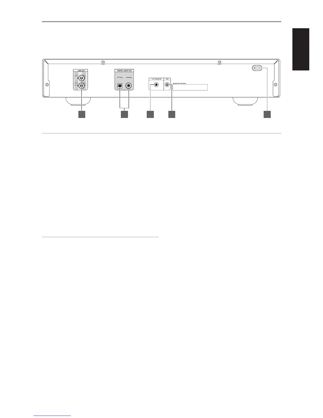
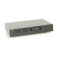
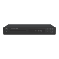
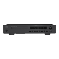
IDENTIFICATION OF CONTROLS
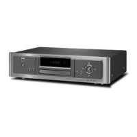
REAR PANEL
1 LINE OUT: Connect to the corresponding analog audio input of an
amplier, receiver or stereo system.
2 DIGITAL OUT (COAXIAL, OPTICAL): The digital playback audio output
signal is available at these ports. Connect the optical or coaxial digital
OUT ports to the corresponding S/PDIF digital input of an amplier,
receiver, computer soundcard or other digital processors.
3 +12V TRIGGER IN: This input allows the C 546BEE to be switched
remotely to standby and ON by ancillary equipment, such as an
amplier, preamp, AV processor, etc. The controlling device must be
equipped with a 12 V trigger output to use this feature. Connect this
+12V-trigger input to the remote component’s corresponding +12V DC
output jack using a mono cable with 3.5mm male plug.
WARNING
If the male plug of the mono cable (with or without +12V DC) is
connected to C 546BEE’s +12V TRIGGER IN, the Standby button in the
front panel as well as the corresponding ON/OFF function keys in the
remote control will be disabled. Unplug the mono cable to maintain
normal power ON/OFF function procedures.
4 IR IN: This input is connected to the output of an IR (infrared) repeater
(Xantech or similar) or the IR output of another component to allow
control of the C 546BEE from a remote location.
5 AC MAINS INPUT: The C 546BEE comes supplied with a separate AC
Mains cable. Before connecting the cable to a live wall socket ensure that
it is rmly connected to the C 546BEE’s AC Mains input socket rst. Always
disconnect the AC Mains cable plug from the live wall socket rst, before
disconnecting the cable from the C 546BEE’s Mains input socket.
ATTENTION!
PleasemakealltheconnectionstoyourC546BEEwiththeunitunplugged.Itisalsoadvisabletopowerdownorunplugallassociatedcomponentswhile
making or breaking any signal or AC power connections.
2 3 4 51
9
ENGLISHFRANÇAISESPAÑOLITALIANODEUTSCHNEDERLANDSSVENSKAРУССКИЙ