EasyManua.ls Logo

Napoleon Ascent 36 User Manual

Napoleon Ascent 36
144 pages
To Next Page IconTo Next Page
Page #1 background imageLoading...
Page #1 background image
FRENCH
PG. 73
W415-1847 / 08.10.18
ADD MANUAL TITLE
Wolf Steel Ltd., 24 Napoleon Rd., Barrie, ON, L4M 0G8 Canada / 103 Miller Drive, Crittenden, Kentucky, USA, 41030
Phone 1 (866) 820-8686 • www.napoleonfi replaces.com • hearth@napoleonproducts.com
CERTIFIED TO THE CANADIAN AND AMERICAN NATIONAL STANDARDS:
CSA 2.22 AND ANSI Z21.50 FOR VENTED DECORATIVE GAS APPLIANCES
INSTALLER:
Leave this manual with the appliance
CONSUMER:
Retain this manual for future reference
ADD PRODUCT CODE HERE (TRADE GOTHIC LT STD FONT)
NATURAL GAS MODELS:
PROPANE GAS MODELS:
Product Name / Code
(MUST use title from Price Book)
ADD ____ ILLUSTRATED
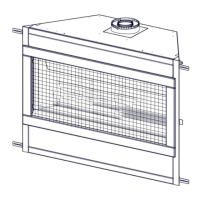
ADD PRODUCT IMAGE
CSA /
INTERTEK
LOGO
SAFETY INFORMATION
- Do not store or use gasoline or other
ammable vapors and liquids in the vicinity of
this or any other appliance.
- WHAT TO DO IF YOU SMELL GAS:
Do not try to light any appliance.
Do not touch any electrical switch; do not
use any phone in your building.
Immediately call your gas supplier from a
neighbour’s phone. Follow the gas
supplier’s instructions.
If you cannot reach your gas supplier, call
the fi re department.
- Installation and service must be
performed by a qualifi ed installer, service
agency, or the supplier.
This appliance may be installed in an aftermarket,
permanently located, manufactured home (USA
only) or mobile home, where not prohibited by
local codes.
This appliance is only for use with the type of gas
indicated on the rating plate. This appliance is
not convertible for use with other gases, unless
a certifi ed kit is used.
FIRE OR EXPLOSION HAZARD
Failure to follow safety warnings exactly
could result in serious injury, death, or
property damage.
WARNING
!
ENGLISH
$10.00
FOR INDOOR USE ONLY
IF INSTALLATION + OPERATION, ADD SERIAL
NUMBER LABEL HERE
IF SEPARATE MANUALS, ADD “PLACE
BARCODE LABEL ON THE OWNER’S MANUAL”
B36NTR / B36NTRE
B36PTR / B36PTRE
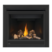
Ascent™ 36
INSTALLATION AND
OPERATION MANUAL
B36 ILLUSTRATED
B36 ILLUSTRÉ
SAFETY BARRIER
ÉCRAN DE PROTECTION

Table of Contents

Questions and Answers:

Napoleon Ascent 36 Specifications

General IconGeneral
Fuel TypeNatural Gas or Propane
IgnitionElectronic Ignition
Vent TypeDirect Vent
Glass TypeCeramic Glass
Log SetRealistic PHAZER® Log Set
EfficiencyUp to 76%

Summary

General Information

1.1 Rates and Efficiencies

Provides data on appliance performance, including input and pressure ratings for different fuel types.

1.2 Installation Overview

Outlines the recommended step-by-step process for installing the appliance.

1.3 Rating Plate Information

Details specifications, certifications, and model-specific information found on the appliance's rating plate.

1.4 Mobile Home Installation

Provides specific requirements and considerations for installing the appliance in mobile homes.

1.5 Dimensions

Presents detailed physical dimensions of the appliance through diagrams and measurements.

Venting Requirements

2.1 Typical Vent Installation

Describes standard procedures and diagrams for top and rear vent installations.

2.2 Special Vent Installations

Covers specific installation types like periscope and corner terminations.

2.3 Minimum Air Terminal Location Clearances

Specifies required clearances for vent terminals based on Canadian and US codes.

2.4 Venting Application Flow Chart

Illustrates a decision tree for determining correct venting configurations based on rise and run.

2.5 Definitions

Explains symbols and terms used in venting calculations and examples.

2.6 Elbow Vent Length Values

Provides equivalent vent lengths for various elbow degrees used in calculations.

2.7 Top Exit Horizontal Termination

Details venting requirements and calculations for top exit horizontal runs.

2.8 Rear Exit Horizontal Termination

Outlines venting requirements and calculations for rear exit horizontal runs.

2.9 Top and Rear Exit Vertical Termination

Explains venting rules and formulas for combined top/rear exit vertical configurations.

2.10 Rear Exit

Provides instructions for installing the rear exit vent components.

2.11 Rear Exit Shield (for Rear Vent Only)

Details the installation of a shield to block the view through the rear venting.

2.12 Top Exit

Describes the procedure for installing the top exit vent configuration.

Rough Framing

3.1 Minimum Framing Dimensions

Specifies minimum dimensions for framing, including clearances for horizontal and vertical vent sections.

3.2 Minimum Enclosure Clearances

Details required clearances between the vent pipe and enclosure materials for top exit.

Venting Installation

4.1 Horizontal Installation

Instructions for installing the firestop assembly and vent shield for horizontal wall termination.

4.2 Vertical Installation

Guidance on installing roof terminals, including firestop placement and sealing.

4.3 Using Either Flexible or Rigid Vent Components

General instructions for connecting and sealing flexible and rigid vent pipes.

4.3.1 Horizontal Air Terminal Installation

Step-by-step guide for connecting the air terminal to the vent pipe for horizontal runs.

4.3.2 Vertical Air Terminal Installation

Instructions for attaching the air terminal connector and flashing for vertical roof installations.

4.3.3 Appliance Vent Connection

Details how to connect the inner and outer flex pipes to the appliance collars.

4.3.4 Horizontal Air Terminal Installation

Specific instructions for connecting rigid vent pipes to the air terminal for horizontal runs.

4.3.5 Vertical Air Terminal Installation

Procedures for attaching elbows and connecting telescopic sleeves for vertical venting.

4.4 Vertical Through Existing Chimney

Guidance on using flex liners within masonry chimneys with adaptors.

4.4.1 Restricting Vertical Vents

Instructions on installing a restrictor plate to modify flame appearance in vertical vents.

Electrical Information

5.1 Electronic Wiring Diagram

Illustrates the electrical connections for the electronic control system and components.

5.2 Battery Back-up Installation

Step-by-step guide for installing and connecting the battery backup system.

Finish Framing

9.1 Minimum Framing Dimensions

Provides diagrams and dimensions for rough framing, including electrical connection and gas inlet locations.

Finishing

10.1 Safety Barrier / Door Removal and Installation

Procedures for safely removing and reinstalling the safety barrier and glass door.

10.2 Front Hood Installation

Instructions for installing the front hood accessory onto the appliance.

10.3 Non-Combustible Facing Material

Guidelines for applying non-combustible facing materials around the appliance opening.

10.4 Minimum Mantel Clearances

Specifies required clearances between the appliance and combustible mantels.

10.5 Recessed Installation

Details clearances and considerations for installing the appliance in a recessed wall.

10.6 Log Placement

Illustrates the correct positioning of logs and other media within the firebox.

10.7 Glowing Embers

Instructions on how to properly place and use glowing embers for a realistic effect.

10.8 Charcoal Embers

Guidance on the placement of charcoal embers for aesthetic enhancement.

10.9 Logo Placement

Instructions for applying the manufacturer's logo to the appliance.

Adjustment

12.1 Pilot Burner Adjustment

Explains how to adjust the pilot flame size and check pressure readings.

12.2 Venturi Adjustment

Details air shutter adjustments and their effect on flame characteristics.

12.3 Flame Characteristics

Describes normal and abnormal flame appearances and when to call a service person.

12.4 Optional Anti Condensation Switch (B36NTRE / B36PTRE only)

Explains the function and operation of the anti-condensation switch for specific models.

Maintenance

13.1 Annual Maintenance

Outlines the procedures for annual servicing, including cleaning and inspections.

13.2 Door Glass Replacement

Provides warnings and instructions for replacing the appliance's glass door assembly.

13.3 Care of Glass

Offers guidance on cleaning the glass, including recommended cleaners and precautions.

Replacement Parts

14.1 Overview

Lists available replacement parts with part numbers, descriptions, and stock status.

14.2 Millivolt Valve Train Assembly

Identifies and lists parts for the millivolt valve train system.

14.3 Electronic Valve Train Assembly

Identifies and lists parts for the electronic valve train system.

Troubleshooting (Electronic)

Troubleshooting (Millivolt)

Warranty

Service History

Related product manuals