29
W415-0661 / 12.07.07
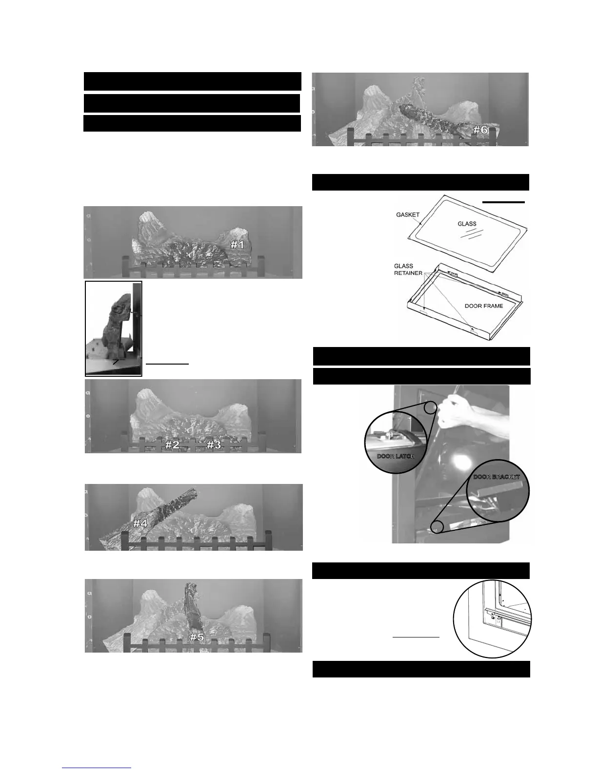
DOOR LATCH
DOOR BRACKET
FIGURE 100
FINISHING
3. Place the bottom of the left crossover log (#4) against the left
fi rebox side and pulled forward to the grate.
The top of the log should rest in the pocket on the back log.
PHAZER
TM
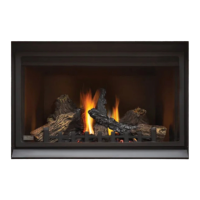
logs and glowing embers exclusive to Napoleon® Fire-
places, provide a unique and realistic glowing effect that is different
in every installation. Take the time to carefully position the glowing
embers for a maximum glowing effect.
Log colours may vary. During the initial use of the fi replace, Log
colours may vary. During the initial use of the fi
replace the colours
will become more uniform as colour pigments burn in during the heat
activated curing process.
LOG PLACEMENT
TAB
SIDEVIEW
FIGURE 93
FIGURE 94
FIGURE 95
FIGURE 96
FIGURE 97
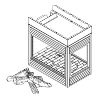
2. Move the two small logs (#2 & #3) into position, lining up the
studs located on the burner with the holes on the bottom of the
logs. Ensure that the small logs sit fl at on the burner.
BGD36CF FINISHING
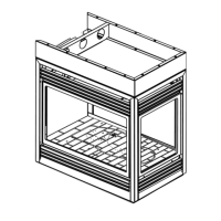
1. Place the back log (#1) onto the log support
tray and in front of the tabs. The tabs maintain
an air space between the log and fi rebox back
to facilitate combustion air fl ow. Ensure that the
back of the log rests against the brackets on
the back wall of the fi rebox.
FIGURE 98
5. Place the bottom of the right crossover log (#6) against the right
fi rebox side and pulled forward to the grate. The top of the log
should rest in the pocket provided on the center log (#5).
BGD42CF FINISHING
DOOR INSTALLATION / REMOVAL
Open the Valve Access
Door. While holding the
door securely, release
the 4 latches
along the top
of the door.
Tilt the door
forward and lift
off of the two
brackets at the
bottom of the door.
When replacing the
door, rest the door on
the brackets ensuring
that lip of the brackets
rest in the groove in
the bottom edge of the
door. Push the door
backward into place
and secure with the 4 latches.
4. Position the base end of the center log (#5) against the middle
grate post with the other end of the log resting in the pocket of the
left crossover log.
REMOVING THE VALVE ACCESS DOOR
1. The valve access door rotates on the
pins attached to the side frame. Lift the
valve access door off the pins to operate
the main glass door.
FIGURE 101
GLASS/DOOR REPLACEMENT
Only available as an assembly complete with frame W010-0770.
Glass not available seperately.
1. Place the door frame
face down careful not to
scratch the paint.
2. Center the gasketed
glass inside the door
frame with the thick side
of the gasket facing up.
3. Bend the glass re-
tainers located along the
edge of the door frame
over the gasket hold-
ing the glass in place.
Careful not to break the
glass.
BGD36CF(G) GLASS/DOOR REPLACEMENT
FIGURE 99
http://www.northlineexpress.com



 To Next Page