32
W415-0661 / 12.07.07
FIGURE 116
FIGURE 117
A
B
FIGURE 118a
C
FIGURE 118b
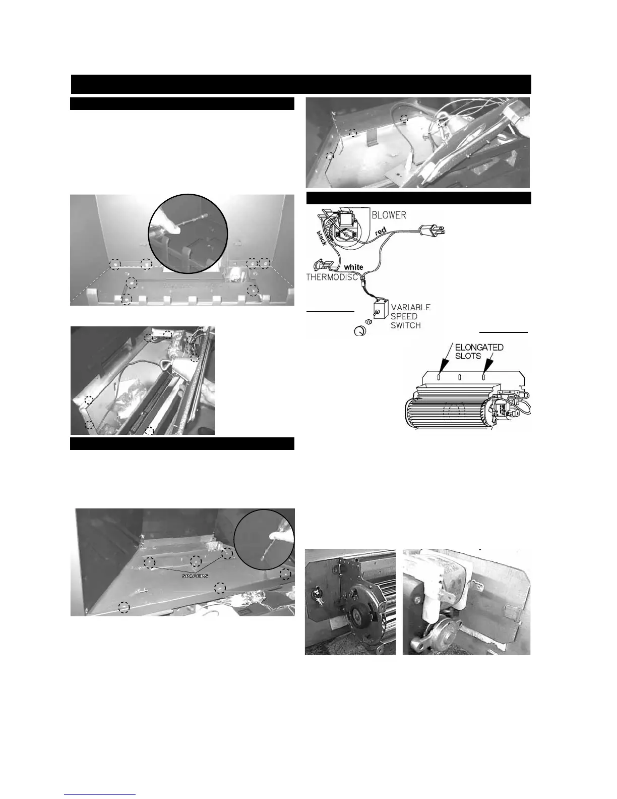
INSTALLING THE BLOWER
INSTALLATION TO BE
DONE BY A QUALI-
FIED INSTALLER and
must be electrically con-
nected and grounded in
accordance with local
codes. In the absence of
local codes, use the cur-
rent CSA C22.1 C
ANADIAN
ELECTRICAL CODE in Cana-
da or the ANSI/NFPA 70
NATIONAL ELECTRICAL CODE
in the United States
If the fi replace was not
previously equipped with
a blower: route a grounded
2-wire, 60hz power cable
to the receptacle / junction
box. At this point, it must
be strain relieved and in-
sulated.
Because the blower is
The three slots on the blower mounting bracket allow ease of adjust-
ment when attaching the blower. For a quiet running blower, do not
allow the assembly to sit on the fi rebox base.
Slide the vibration reducing pad (A) into the clip (C) and up against
the threaded stud (B) at the other end. The blower must be able to
be positioned entirely onto the pad.
To ease installation of the blower, remove the hinge screen and valve
control door (lower louvres) from the base of the fi replace.
Tilt the blower onto its side. Slide it past the controls and into the clip
(C). Secure to the threaded stud using the lock washer and wing nut
provided. Ensure that the blower does not touch the fi replace base
or the fi rebox.
5. Remove the 8 perimeter screws as illustrated in Fig. 112 and lift
out the burner base. (The gas line fl ex-connector should provide
suffi cient movement
to permit shifting the
burner assembly to the
side).
6. Reverse procedure
to re-assemble.
OPTIONAL BLOWER INSTALLATION
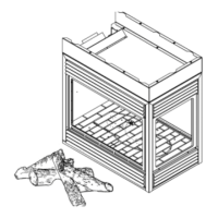
BGD36CF(G) ACCESSING THE BLOWER
1. Remove the valve access door.
2. Open the main door.
3. Carefully remove the logs.
3a. (BGD36CFG) Carefully remove the glass and glass ember
tray.
4. Remove the 7 screws illustrated in Fig. 1
12 and lift out the log
support.
4a. (BGD36CFG)
Remove the top defl ector and porcelain panels
from the fi
rebox. (See Figure 109).
FIGURE 112
FIGURE 113
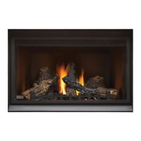
BGD42CF ACCESSING THE BLOWER
1. Remove the main door using the instructions on Pg #29.
2. Carefully remove the logs.
3. Remove the grate by lifting it off of the two securing pins.
4. Remove the 6 screws illustrated in Fig. 113 and lift out the
log support. Be careful not to lose the spacers for the screws
indicated.
5. Remove the 7 perimeter screws as illustrated in Fig. 115 and lift
out the burner base. (The gas line
fl ex-connector should provide suffi cient movement to permit shift-
ing the burner assembly to the side).
6. Reverse procedure to re-assemble.
SPACERS
FIGURE 114
FIGURE 115
http://www.northlineexpress.com
 Loading...