34
W415-0661 / 12.07.07
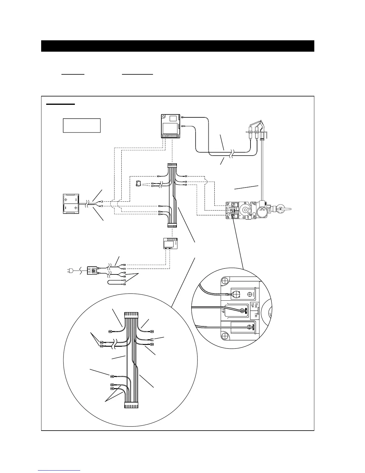
BGD36CFG BURNER SWITCH / WIRING DIAGRAM
A wall switch must be installed in a convenient location for the burn-
er operation.
The recommended maximum lead length depends on wire size:
WIRE SIZE MAX. LENGTH
14 gauge 100 feet
16 gauge 60 feet
18 gauge 40 feet
A 20’ length of millivolt wire is connected to the gas valve for the
burner wall switch. However if a greater length is required route
2-strand (solid core) wire through the electrical hole located at the
bottom left side of the unit.
FIGURE 125
BATTERY
HOLDER
GAS VALVE
PILOT
ASSEMBLY
IGNITION
MODULE
PILOT
GAS LINE
Orange
(I)
[through
independent
conduit]
Yellow
(S)
[through
Gas line
conduit]
AC ADAPTOR
BATTERY
RELAY
Red (3 Volt)
Red
Black
WIRE
HARNESS
NOTE: WIRE TAGS
ARE BRACKETED
Brown
(SWI)
Black
(-)
Red
(+)
Green x2
(TH)
Orange x2
(THTP)
Black
Yellow
Blue
Black
(TP)
MODULE
PLUG
RELAY
PLUG
Black
Green
Orange
Black (12 Volt)
To Accent Light &
Night Light
TM
Switch
MAIN
BURNER SWITCH
*
Main Burner Switch
http://www.northlineexpress.com
 Loading...