36
W415-0773 / E / 03.13.12
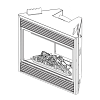
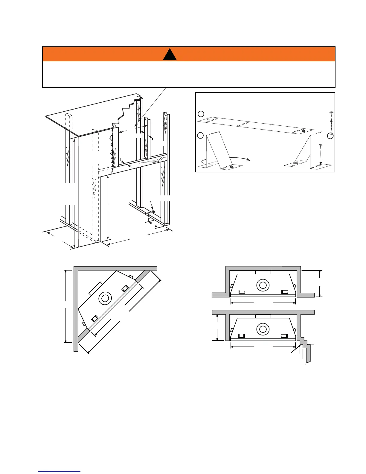
STAND-OFF ASSEMBLY
Bend and secure the top stand-off(s) as illustrated:
A
B
C
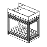
6.1.1 MINIMUM FRAMING DIMENSIONS
37
3
/4”
38
3
/4”
3”
14
1
/2”
63”
(TOP EXIT)
42
1
/4”
(REAR EXIT)
ENCLOSURE
TOP
FINISHING
MATERIAL
5
1
/2”
GAS
INLET
LOCATION
1
1
/2”
MAX
14”
MINIMUM
3
1
/2”
MAX
TOP EXIT INSTALLATION
SHOWN
FOR TOP EXIT APPLICATIONS: DO NOT BUILD INTO THIS AREA. IT MUST BE LEFT CLEAR TO
PROVIDE ADEQUATE CLEARANCE FOR THE VENT. IN THIS 14" WIDE AREA CENTRED ALONG THE
FRONT OF THE APPLIANCE, NO COMBUSTIBLES ARE ALLOWED.
!
WARNING
Combustion protrusions such as mantels and shelves may occur at or after a minimum distance of 2" away from the side of
the appliance.
Thereafter, the depth of any protrusions must be equal to or less than the distance from the side of the appliance up to a
depth of 6", after which no greater clearance than 6" is required. This can be considered a side wall with no length boundary.
36
3
/4"
37
3
/4"
52"
37
3
/4"
14
1
/2"
14
1
/2"
INSIDE
CHASE
37
3
/4"
OUTSIDE
CHASE
4"
2"
SIDE
WALL
2"
4"
6"
PROTRUSION