EN
W415-2753 / A / 07.20.20
19
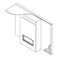
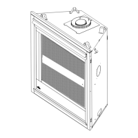
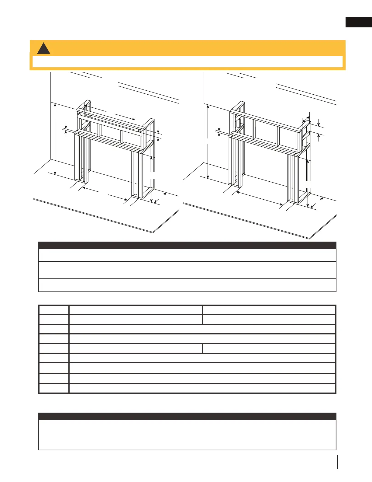
fi nish framing - after appliance installation
recessed
Ref EX36 EX42
I
39 3/4” 45 3/4”
C
22 1/4”
D
6”
H
43 3/4” 47 3/4”
L
72”
Q*
2” min and 3” max
(Q x R)*
112 sq. in. min.
M**
3”, 6” max
* ONLY APPLICABLE TO OPTION 2, 3 and 5 - Opening must be centered in enclosure on appliance. Dimensions represent
fi nished sizes and where applicable should be adjusted to include fi nish material thickness.
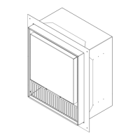
minimum framing
Finish framing must be built after appliance has been placed in its fi nal position and venting connected.
This confi guration also requires recess area to use non-combustible facing due to close proximity to
vent.
note:
Installation Option 2 illustrated
note:
The Elevation series requires a minimum enclosure height (as illustrated) measured from the bottom of the ap-
pliance. For temperature requirements, this area must be left unobstructed. Some venting confi gurations that
require more vertical rise will require a larger enclosure to provide minimum vertical clearance between vent
pipes and combustibles.
Recessed volume must be added to the overal size of enclosure.
Q
M
H
C
D
I
D
L
R
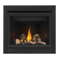
Dynamic Heat Control™
side air outlet opening
Installation Option 5 illustrated
D
D
L
Dynamic Heat Control™
front air outlet opening
C
H
M
!
WARNING
• Shaded components (fi nish framing) must be non-combustible materials.
Q
R
 Loading...