1-10 General Information
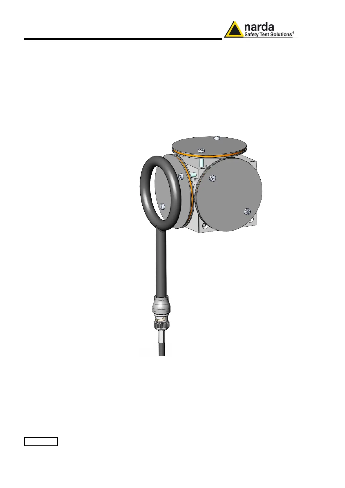
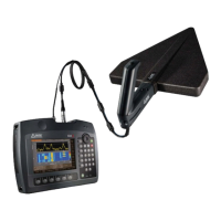
As depicted above, the magnetic sensor system is composed by three
magnetic loops positioned orthogonal each other. The electric sensor
system is composed by three orthogonal parallel plates capacitors installed
on the opposite side of the magnetic loops
.
The geometric structure of the Narda probes, with sensors placed on the
peripheral faces of the cube, shows the same behavior as one with the
sensors accumulated in the center, when measuring far fields.
Moreover, this provides the opportunity to evaluate also very nearby fields,
albeit with all the limitations that this entails, knowing exactly where the
single sensor is, and allowing to minimize the contribution of the others.
References
[1] ISO/IEC “Guide to the expression of uncertainty in measurement” JCGM 100:2008 GUM 1995
with minor correction – International Organization for Standardization.
[2] CEI-IEC 61786-1 ed. 1.0 “Measurement of DC magnetic, AC magnetic and AC electric fields from
1 Hz to 100 kHz with regard to exposure of human beings – Part 1: Requirements for measuring
instruments.
[3] IEEE Std 1309™-2005 (revision of IEEE Std 1309-1996) “IEEE Standard for Calibration of
Electromagnetic Field Sensors and probes, Excluding Antennas, from 9 kHz to 40 GHz”.
[4] EA European co-operation for Accreditation – Public Reference EA-4/02 M:2013