EMC
L/L1
N/L2
F+
F-
AN1
AN2
AN3
AN4
+15
0V
+10
0V
IN1
IN2
IN3
IN4
COMBO
G S1+ S1-
LINE
G S2+ S2-
MODBUS
STATUS
ALARM
NO1 COM1 NC1
NO2 COM2 NC2
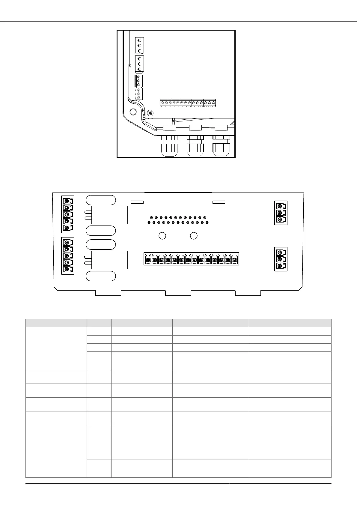
Control connections for size 2 devices
IN4
IN3
IN2
IN1
0V
+15V
0V
+15V
0V
+10V
AN4
AN3
AN4
AN3
MODBUS
COMBO
G
S1-
S1+
G
S2-
S2+
ALARM
NO1 COM1 NC1
STATUS
NO2 COM2 NC2
Type Description Functionality Comments
Analog inputs AN1 4-20 mA Sensor 1 -
AN2 4-20 mA Sensor 2 -
AN3 0-10 V External set value
AN4 0-10 V External frequency
External set value 2
Power Supply +15V 15 VDC, max 100 mA Power supply for 4-20 mA ana-
log inputs
Do not use as a power supply for
the digital inputs!
Power Supply +10V 10 VDC, max 3 mA Power supply for 0-10 V analog
inputs
Do not use as a power supply for
the digital inputs!
Signal GND 0V Insulated Signal GND for analog and digi-
tal inputs
-
Digital inputs IN1 Active low Motor start and stop Programmable as Normally Open
or Normally Closed.
IN2 Active low Motor start and stop
Switching of set value 1 and 2
Switching of work frequency 1
and 2
Programmable as Normally Open
or Normally Closed.
IN3 Active low Motor start and stop
Switching of sensors 1 and 2
Programmable as Normally Open
or Normally Closed.
MIDA
27