MIDA 325 , MIDA 330 , MIDA 338 , MIDA 344 ,MIDA 425 , MIDA 430 , MIDA 438 , MIDA
444
L1 L2 L3
LINE
U V W
MOTOR
EMCEMC
DC IN/DC IN/
BRAKEBRAKE
DC -DC -
R -R -
R +R +
DC +DC +
L1 L2 L3
LINE
U V W
MOTOR
EMCEMC
DC IN/DC IN/
BRAKEBRAKE
DC -DC -
R -R -
R +R +
DC +DC +
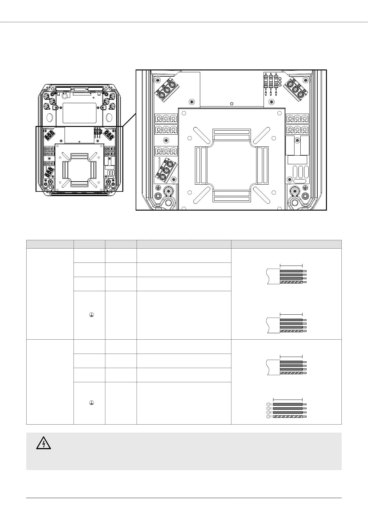
A [mm] Pre-insulated cable lug Stripping diagram
Power Supply
LINE
L1
180
(120)
Tip
Wall installation (through lower cable glands)
Installation on motor (through lateral cable
glands)
L2
180
(120)
Tip
L3
180
(120)
Tip
P.E.
180
(120)
Eyelet for M4 screw
Motor
MOTOR
U
180
(180)
Tip
Wall installation
Installation on board the engine
V
180
(180)
Tip
W
180
(180)
Tip
P.E.
180
(180)
Eyelet for M4 screw
DANGER
In size 2 devices, the DL1, DL2, DL3 LEDs next to the power supply terminal block indicate the
presence of voltage in the input phases. Do not touch the device and its components for any reason
if one or more LEDs are on.
7.5.2. Control connections
Control connections for size 1 devices
MIDA
26