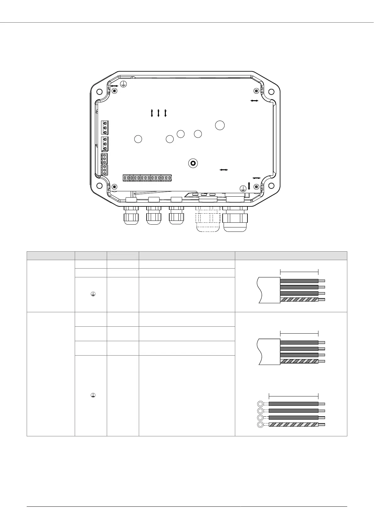
7.5.1. Power connections
MIDA 203 , MIDA 205 , MIDA 207
MOTOR
W
V
U
EMC
L/L1
N/L2
F+
F-
AN1
AN2
AN3
AN4
+15
0V
+10
0V
IN1
IN2
IN3
IN4
COMBO
MODBUS
STATUS
ALARM
G S2+ S2-
G S1+ S1-
NO1 COM1 NC1
NO2 COM2 NC2
LINE
A [mm] Pre-insulated cable lug Stripping diagram
Power Supply
LINE
L1/L 70 6.3 x 0.8 mm female Faston
L2/N 70 6.3 x 0.8 mm female Faston
P.E.
70 6.3 x 0.8 mm female Faston
Motor
MOTOR
U
120
(200)
6.3 x 0.8 mm female Faston
Wall installation
Installation on board the engine
V
120
(200)
6.3 x 0.8 mm female Faston
W
120
(200)
6.3 x 0.8 mm female Faston
P.E.
180
(200)
6.3 x 0.8 mm female Faston
MIDA
23