Chapter 4 Programming
©
National Instruments Corporation 4-57 PCI E Series RLPM
they determine if the pending interrupt belongs to their device. If it does
not, the ISR must pass control to the next ISR in the chain.
In order to determine if a PCI E Series board has a pending interrupt do the
following:
1. Perform a 32 bit memory read from BAR0 + 0x14.
2. Check the status of bit 31 (highest order bit in the register). If this bit
is high the PCI E Series board is currently asserting an interrupt.
DMA Programming
You can program your PCI E Series board so that the analog input, analog
output, or general purpose counter/timers can generate DMA requests
under appropriate circumstances. There are four logical DMA
channels—A, B, C, and D.
Each logical channel, in turn, can service either analog input, analog
output, or the general-purpose counter/timers. You must program the AO
AI Select Register (address 0x09) and the G0G1 Select Register (address
0x0B) to assign particular logical channels to either AI, AO, or GPCTs.
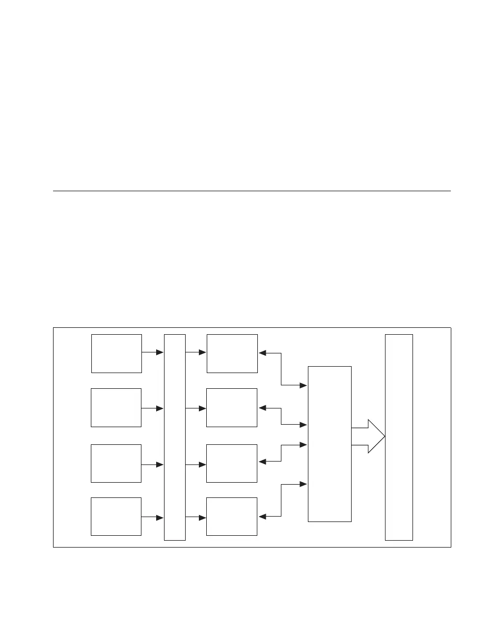
Figure 4-2 shows the three-stage DMA structure.
Figure 4-2.
DMA Structure
Analog
Input
Analog
Output
GPCT0
GPCT1
Logical Channel Assignment
PCI BUS
MINI-MITE
Logical
DMA
Channel A
Logical
DMA
Channel B
Logical
DMA
Channel C
Logical
DMA
Channel D
 Loading...