©
National Instruments Corporation 2-1 PCI E Series RLPM
2
Theory of Operation
This chapter contains a functional overview of the PCI E Series boards and
explains the operation of each functional unit making up the PCI E Series
boards.
Functional Overview
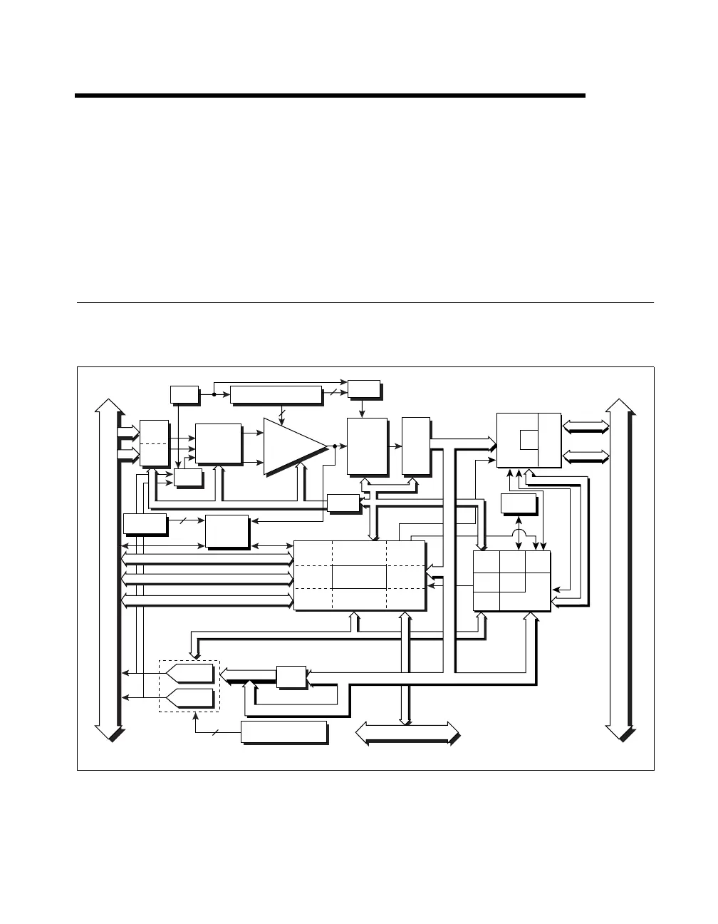
The block diagram in Figures 2-1 through 2-5 give a functional overview
of each PCI E Series board.
Figure 2-1.
PCI-MIO-16E-1, PCI-MIO-16E-4, and PCI-6071E Block Diagram
Timing
PFI / Trigger
I/O Connector
3
2
2
RTSI Bus
Digital I/O (8)
12-Bit
Sampling
A/D
Converter
Configuration
Memory
REF
Buffer
+
Programmable
Gain
Amplifier
–
Calibration
Mux
Mux Mode
Selection
Switches
Analog
Muxes
Voltage
REF
Calibration
DACs
4
Calibration
DACs
DAC0
DAC1
DAQ - STC
Analog Input
Timing/Control
Analog Output
Timing/Control
Digital I/O
Trigger
Counter/
Timing I/O
RTSI Bus
Interface
DMA/
Interrupt
Request
Bus
Interface
(8)*
(8)*
AI Control
IRQ
DMA
AO Control
DAC
FIFO
Data (16)
Trigger Level
DACs
Analog
Trigger
Circuitry
Data (16)
ADC
FIFO
Trigger
PCI Bus
EEPROM
Address/Data
Control
Data (16)
Analog
Input
Control
EEPROM
Control
DMA
Interface
MIO
Interface
DAQ-STC
Bus
Interface
Analog
Output
Control
I/O
Bus
Interface
MINI
MITE
Generic
Bus
Interface
PCI
Bus
Interface
Address (5)
*(32) for the PCI-6071E
 Loading...