© National Instruments | 1-35
NI cDAQ-9132/9133/9134/9135/9136/9137 User Manual
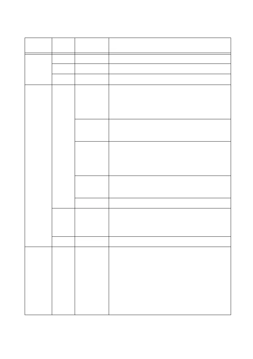
Table 1-6. LED Indications
LED
LED
Color LED State Indication
POWER Green Solid The cDAQ controller is powered from the V1 input.
Yellow Solid The cDAQ controller is powered from the V2 input.
—
Off The controller is not powered.
STATUS Yellow 2 flashes
every few
seconds
The controller has detected an error in its software. This
usually occurs when an attempt to upgrade the software is
interrupted. Refer to the Measurement & Automation
Explorer Help for information about installing software on
the controller.
3 flashes
every few
seconds
The controller is in safe mode. Refer to the Measurement &
Automation Explorer Help for information about safe mode.
4 flashes
every few
seconds
The software has crashed twice without rebooting or cycling
power between crashes. This usually occurs when the
controller runs out of memory. Review your RT VI and
check the memory usage. Modify the VI as necessary to
solve the memory usage issue.
Continuously
flashing
The controller either booted into an unsupported operating
system, was interrupted during the boot process, or detected
an unrecoverable software error.
Solid The controller is booting up.
Red Continuously
flashing
An internal power supply has failed. Check front-panel I/O
and C Series module connections for shorts. Remove any
shorts and power cycle the controller. If the problem
persists, contact National Instruments.
— Off Normal operation.
USER1,
USER2
Green/
yellow
— USER LEDs are controlled directly from your application.
You can define the USER1 and USER2 LEDs to meet the
needs of your application. You can use the system hardware
property node from the NI System Configuration API to
write a state to the USER LEDs.
(NI cDAQ-9132/9133/9134/9135/9136/9137 for
LabVIEW Real-Time)
You can also define a USER LED
in LabVIEW Real-Time by using the RT LEDs VI. For more
information about the RT LEDs VI, refer to the LabVIEW
Help.
 Loading...