Chapter 7 Counters
M Series User Manual 7-34 ni.com
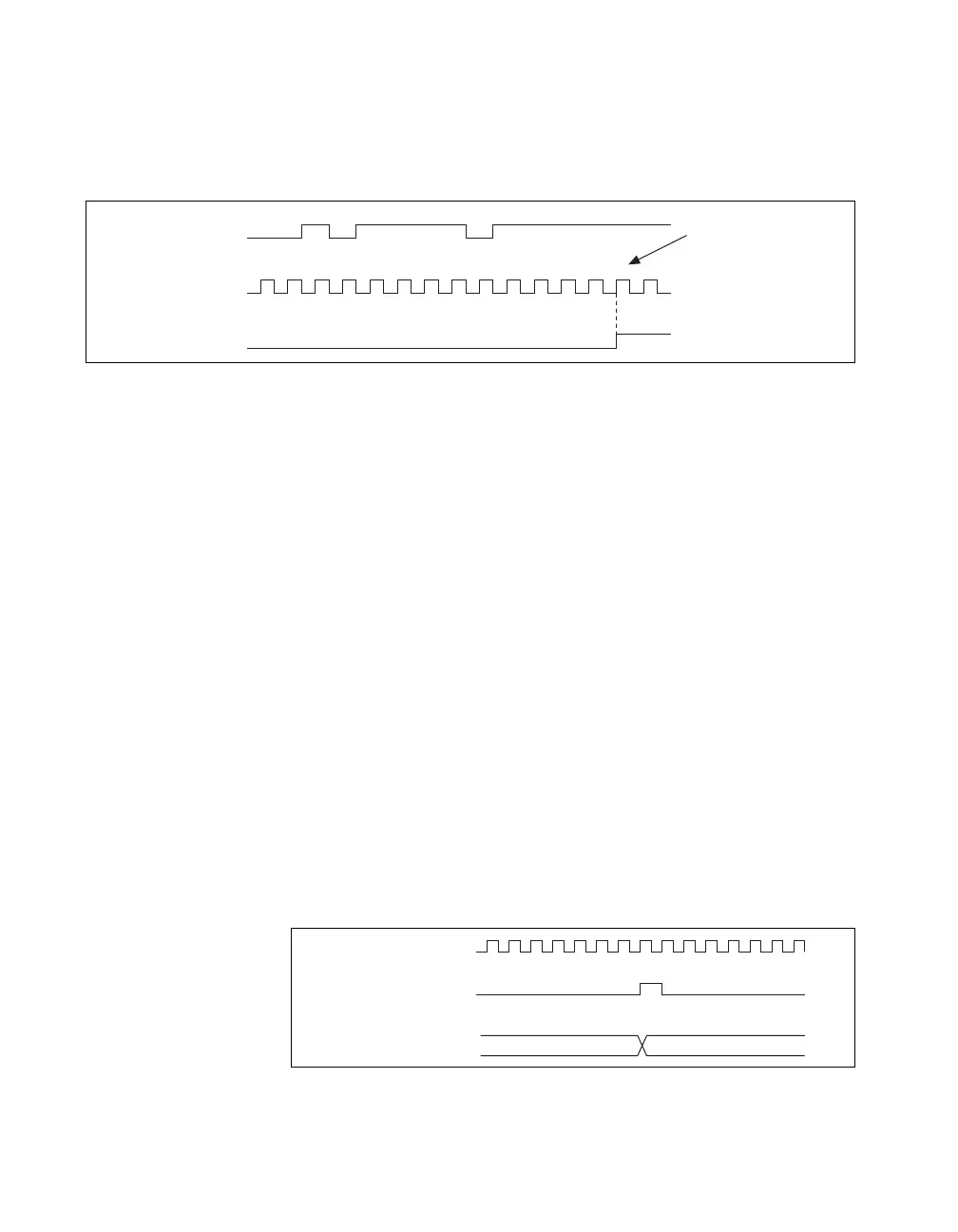
The filter setting for each input can be configured independently. On power
up, the filters are disabled. Figure 7-28 shows an example of a low to high
transition on an input that has its filter set to 125 ns (N = 5).
Figure 7-28. Filter Example
Enabling filters introduces jitter on the input signal. For the 125 ns and
6.425 µs filter settings, the jitter is up to 25 ns. On the 2.56 ms setting, the
jitter is up to 10.025 µs.
When a PFI input is routed directly to RTSI, or a RTSI input is routed
directly to PFI, the M Series device does not use the filtered version of the
input signal.
Refer to the KnowledgeBase document, Digital Filtering with M Series,
for more information about digital filters and counters. To access this
KnowledgeBase, go to
ni.com/info and enter the info code rddfms.
Prescaling
Prescaling allows the counter to count a signal that is faster than the
maximum timebase of the counter. M Series devices offer 8X and 2X
prescaling on each counter (prescaling can be disabled). Each prescaler
consists of a small, simple counter that counts to eight (or two) and rolls
over. This counter can run faster than the larger counters, which simply
count the rollovers of this smaller counter. Thus, the prescaler acts as a
frequency divider on the Source and puts out a frequency that is one-eighth
(or one-half) of what it is accepting.
Figure 7-29. Prescaling
1 2 3 1 4 1 2 3 4 5
RTSI, PFI, or
PXI_STAR Terminal
Filter Clock
(40 MHz)
Filtered Input
Filtered input goes
high when terminal
is sampled high on
five consecutive filter
clocks.
External Signal
Counter Value
Prescaler Rollover
(Used as Source
by Counter)
01
 Loading...