Chapter 5 Analog Output
M Series User Manual 5-6 ni.com
With non-regeneration, old data will not be repeated. New data must be
continually written to the buffer. If the program does not write new data to
the buffer at a fast enough rate to keep up with the generation, the buffer
will underflow and cause an error.
Analog Output Triggering
Analog output supports two different triggering actions:
• Start trigger
• Pause trigger
An analog or digital trigger can initiate these actions. All M Series devices
support digital triggering, but some do not support analog triggering. To
find your device’s triggering options, refer to the specifications document
for your device. Refer to the AO Start Trigger Signal and AO Pause Trigger
Signal sections for more information about these triggering actions.
Connecting Analog Output Signals
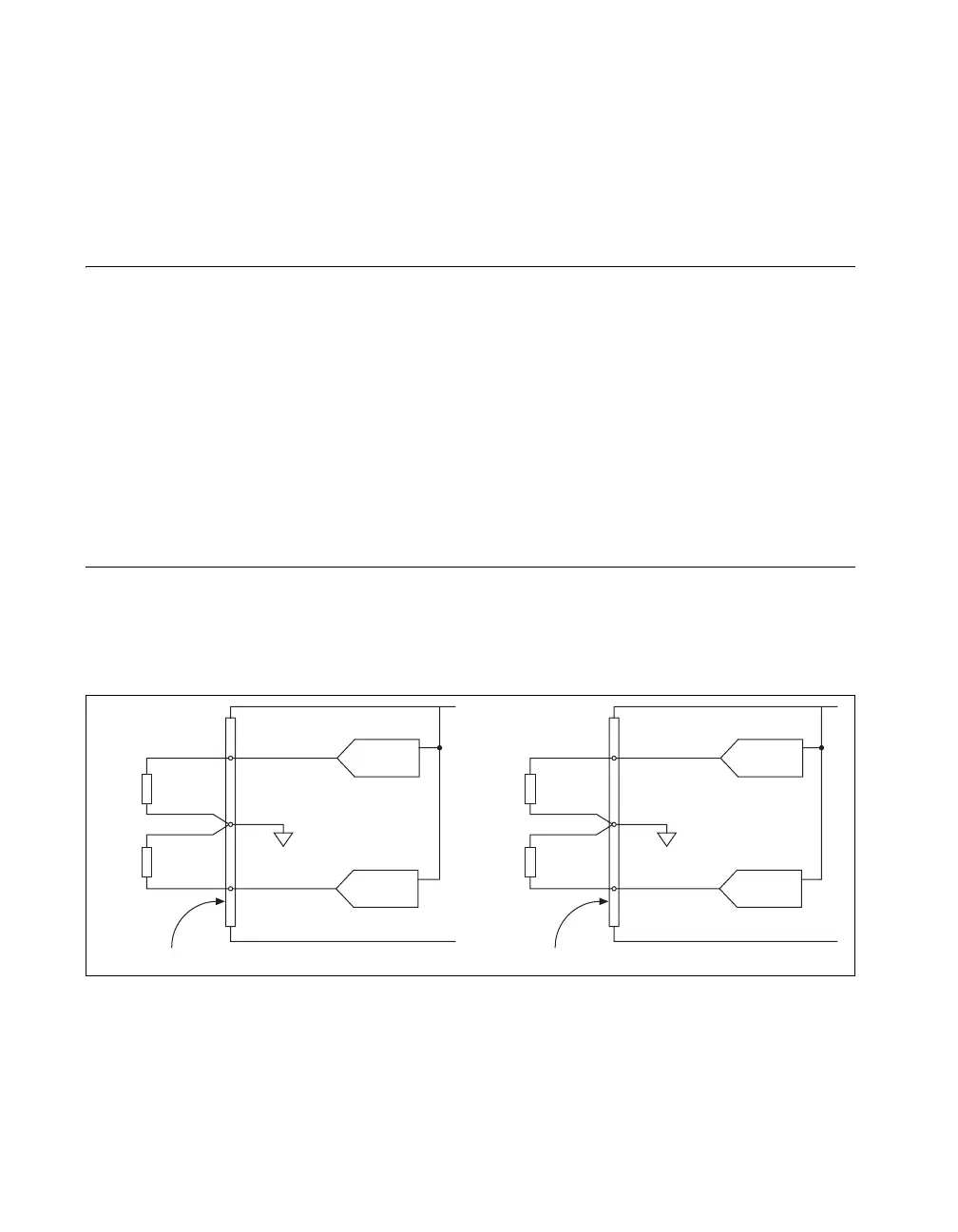
AO <0..3> are the voltage output signals for AO channels 0, 1, 2, and 3.
AO GND is the ground reference for AO <0..3>.
Figure 5-2 shows how to make AO connections to the device.
Figure 5-2. Analog Output Connections
Load
Load
V OUT
V OUT
+
–
+
–
AO GND
AO 3
Analog Output Channels
AO 2
Channel 3
Connector 1 (AI 16–31)
Channel 2
M Series Device
Load
Load
V OUT
V OUT
+
–
+
–
AO GND
AO 1
Analog Output Channels
M Series Device
AO 0
Channel 1
Channel 0
Connector 0 (AI 0–15)

 Loading...