Appendix B Timing Diagrams
© National Instruments Corporation B-13 M Series User Manual
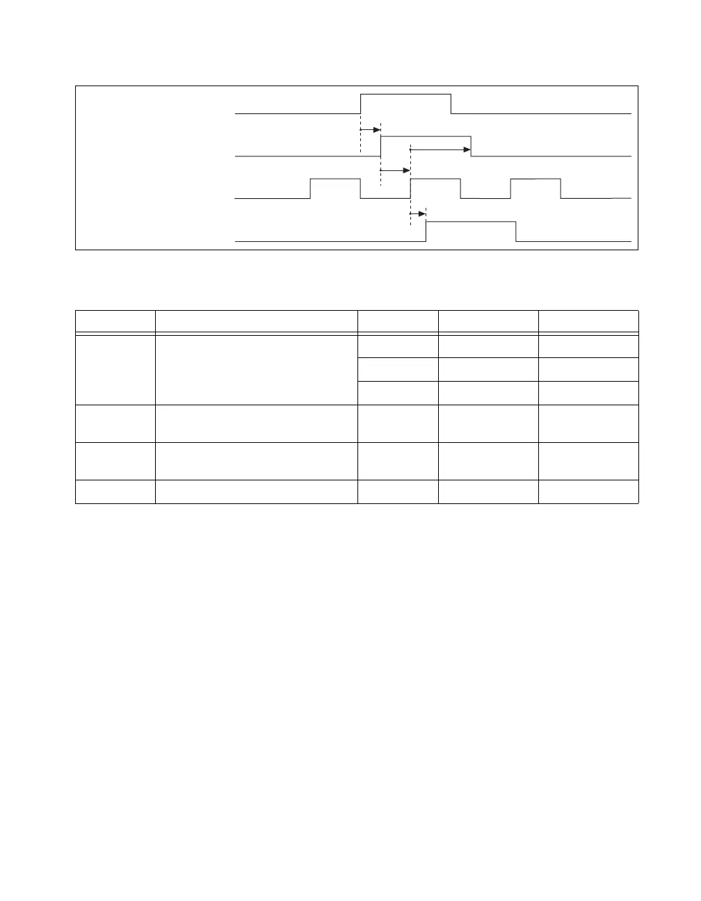
Figure B-12. Sample Clock Timebase Timing Diagram
Reference Trigger
Use the Reference Trigger to stop the acquisition. It is normally used in
pretrigger acquisitions; it is necessary to acquire data before and after the
trigger. The Reference Trigger signals the time when the AI timing engine
starts counting the number of posttrigger conversions to take before
stopping. The Reference Trigger can come from external or internal
sources and its source is selected with a multiplexer. Its output is called the
Selected Reference Trigger.
Table B-6. Sample Clock Timebase Timing
Time Description Line Min (ns) Max (ns)
t
18
Delay to Selected Start PFI 3.4 8.8
RTSI 3.3 8.5
STAR 2.7 5.7
t
19
Selected Start Setup/Hold Time
(to Sync Sample Clock Timebase)
— 1.5 —
t
20
Selected Start Setup/Hold Time
(to Sync Sample Clock Timebase)
— 0 —
t
21
Sync Sample Clock Timebase to SI_Start — 0.9 2.2
_i
Selected Start
Sync Sample Clock Timebase
SI Start
t
18
t
21
t
19
t
20
 Loading...