Appendix B Timing Diagrams
© National Instruments Corporation B-15 M Series User Manual
Sample Clock
Sample Clock signals the start of a sample (which, in turn, is a set of
converts). Sample Clock is generated from external or internal sources. The
main internal source is the terminal count (TC) of the SI counter that runs
on the Sample Clock Timebase signal. All the sources for Sample Clock are
at the _i level and are selected using a multiplexer. The output of this
multiplexer is called Selected Sample Clock.
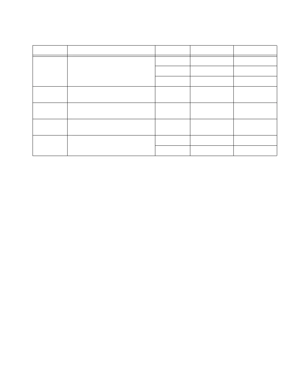
Table B-7. Reference Trigger Timing
Time Description Line Min (ns) Max (ns)
t
22
Delay to the Selected Reference Trigger PFI 3.6 8.9
RTSI 3.4 8.4
STAR 2.9 5.6
t
23
Selected Reference Trigger Setup
(to Sync Convert Clock Timebase)
— 1.5 —
t
24
Selected Reference Trigger Hold
(to Sync Convert Clock Timebase)
— 0 —
t
25
Sync Convert Clock Timebase to
Reference Trigger
— 0.9 2.2
t
26
Reference Trigger to POUT PFI 0.8 2.3
RTSI 0.8 1.9
 Loading...