Appendix B Timing Diagrams
M Series User Manual B-28 ni.com
Output Timing
The analog output timer has three possible trigger outputs—Start Trigger,
Pause Trigger, and Sample Clock. The delays presented in this section
assume a 200 pF load on PFI lines and a 50 pF load on RTSI lines. Actual
delays will vary with the actual load. The two numbers given for each
condition represent the variation from the best case and worst case
terminals.
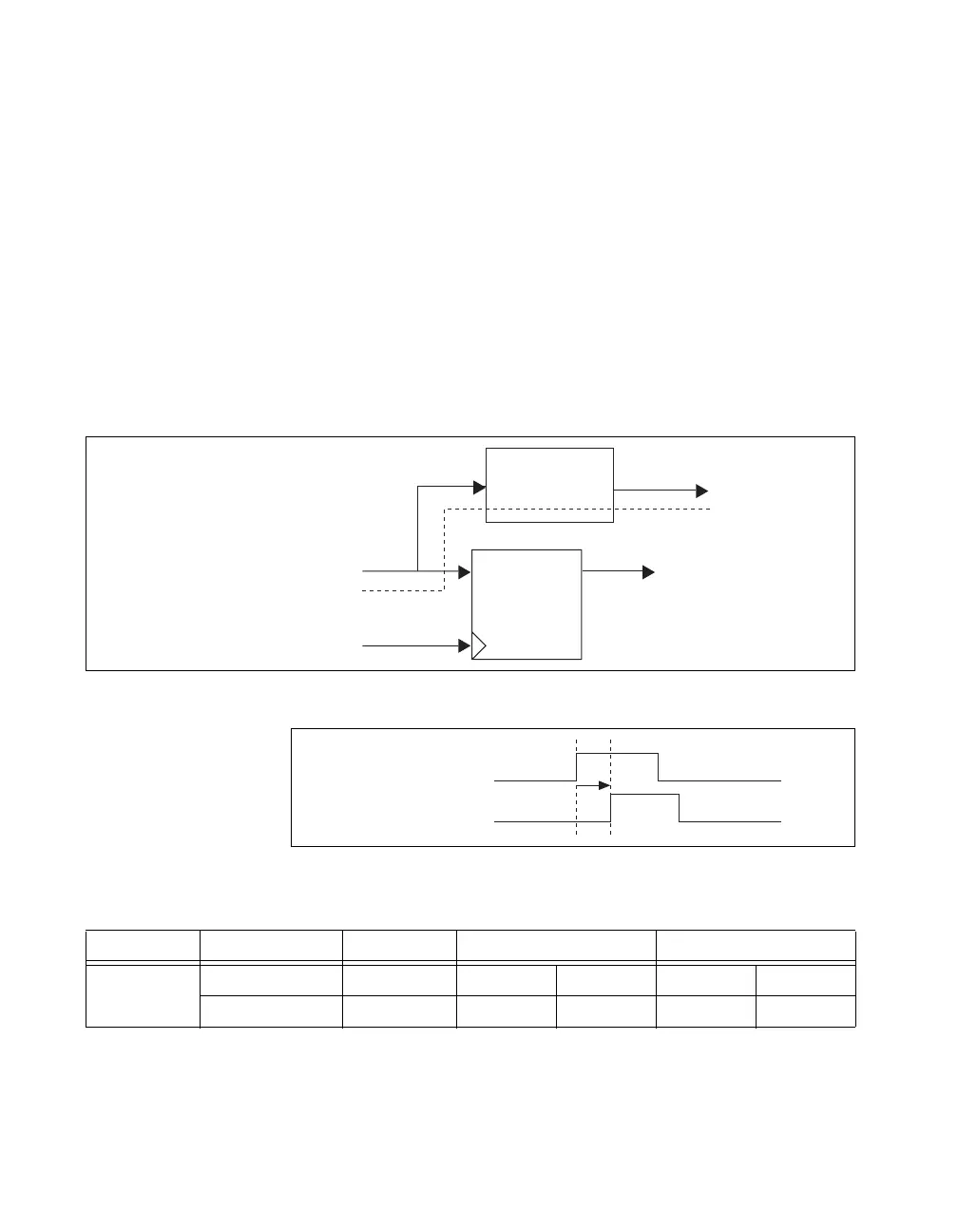
Start Trigger
As an output, the Start Trigger is routed as an asynchronous pulse. The
actual signal that gets routed is the Selected Start signal, so there is no
synchronous delay involved.
Figure B-31. Start Trigger Path
Figure B-32. Start Trigger Output Delay Timing Diagram
Table B-19. Start Trigger Output Delay Timing
Time From To Min (ns) Max (ns)
t
12
Selected Start PFI 8.1 9.1 27.1 30.8
Selected Start RTSI 7.5 7.7 17.9 18.5
Selected Start
Sync Sample Clock Timebase
D Q To Internal Logic
Routing Logic
RTSI, PFI
Selected Start
PFI/RTSI Terminal
t
12

 Loading...