Back Panel
0 1
PWR
REF
IN
PPS
OUT
TRIG
5V DC
REF
OUT
1G/10G ETH
3.3 V +15 dBm
MAX
9-16V DC
7.5 A MAX
SFP+Ports
PCIe x4
TRIG
3.3V
IN
5V MAX
PPS GPS
ANT
–15 dBm
MAX
.
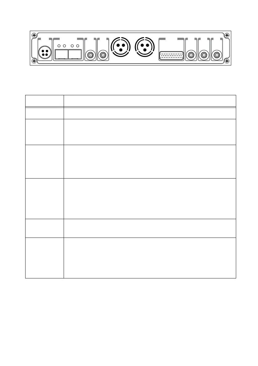
Table 4. Connector Descriptions
Connector Description
PWR Input that accepts a 9 V to 16 V, 6 A external DC power connector.
1G/10G ETH Ethernet port that accepts 1G SFP modules and 10G SFP+ modules. With a
1G ETH module inserted, the ports accept gigabit Ethernet-compatible
cables (Category 5, Category 5e, or Category 6).
REF OUT Output terminal for an external reference signal for the LO on the device.
REF OUT is a female SMA connector with an impedance of 50 Ω, and it is
a single-ended reference output. The output signal at this connector is
10 MHz at 3.3 V.
REF IN Input terminal for an external reference signal for the LO on the device.
REF IN is a female SMA connector with an impedance of 50 Ω, and it is a
single-ended reference input. REF IN accepts a 10 MHz signal with a
minimum input power of 0 dBm (0.632 V
pk-pk
) and a maximum input
power of 15 dBm (3.56 V
pk-pk
) for a square wave or sine wave.
PCIe x4 Port for a PCI Express Generation 1, x4 bus connection through an MXI
Express four-lane cable.
PPS TRIG
OUT
Output terminal for the pulse per second (PPS) timing reference. PPS TRIG
OUT is a female SMA connector with an impedance of 50 Ω, and it is a
single-ended input. The output signal is 0 V to 3.3 V TTL. You can also use
this port as triggered output (TRIG OUT) that you program with the PPS
Trig Out I/O signal.
18 | ni.com | USRP-2950/2952/2953/2954/2955 Getting Started Guide
 Loading...