Synchronizing Multiple Devices (Optional)
To set up a higher channel-count system, you can synchronize two or more USRP RIO devices
so that they share clock and pulse per second (PPS) signals.
Note Synchronizing multiple USRP RIO devices requires a CDA-2990 accessory.
Ensure that all hardware is set up as previously described.
1. Connect the REF IN port of the USRP RIO device to the first 10 MHz OUT port of the
CDA-2990 using a standard SMA (m)-to-SMA (m) cable.
2. Connect the PPS TRIG IN port of the USRP RIO device to the PPS OUT port of the
CDA-2990 using a standard SMA (m)-to-SMA (m) cable.
3. Repeat steps 1 and 2 to synchronize additional USRP RIO devices using the additional
ports on the CDA-2990 (optional).
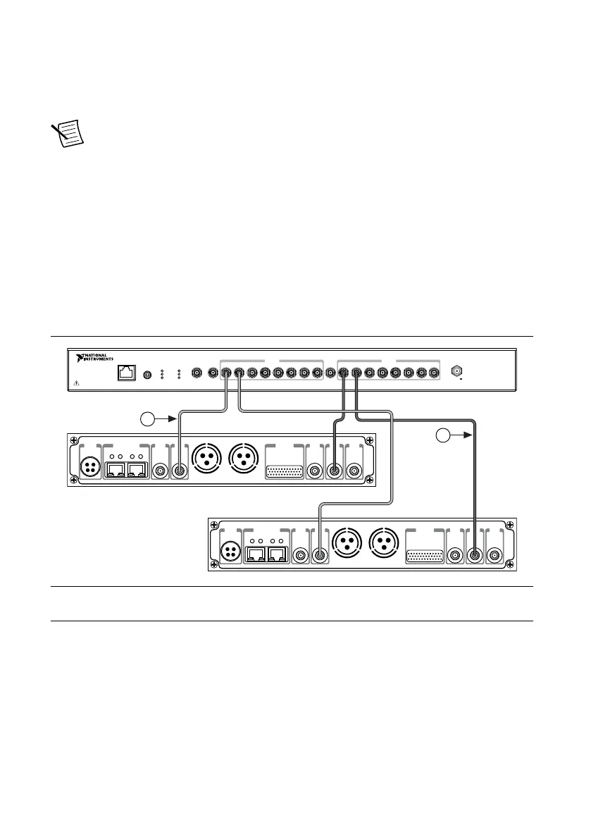
The completed hardware setup for two USRP RIO devices is shown in the following
figure.
Figure 3.
USRP Device Synchronization Configuration
2
CDA-2990
Designed by Ettus ResearchDesigned by Ettus Research
3 4 5 621
7
8 7 83 4 5 621
PPS OUT10 MHz OUT PPS OUT
POWER
GPS LOCK
PPS
STATUS
EXTERNAL
INTERNAL
ETHERNET
GPS ANT
INPUT
PRIMARY REF
INTERNAL
EXTERNAL
EXT 10 MHz
INPUT
EXT PPS
INPUT
POWER
8 Channel Clock Distribution Module
6 – 15 V
6 W MAX
0 1
PWR
REF
IN
PPS
OUT
TRIG
5V DC
REF
OUT
1G/10G ETH
3.3 V +15 dBm
MAX
9-16V DC
7.5 A MAX
SFP+Ports
PCIe x4
TRIG
3.3V
IN
5V MAX
PPS GPS
ANT
–15 dBm
MAX
0 1
PWR
REF
IN
PPS
OUT
TRIG
5V DC
REF
OUT
1G/10G ETH
3.3 V +15 dBm
MAX
9-16V DC
7.5 A MAX
SFP+Ports
PCIe x4
TRIG
3.3V
IN
5V MAX
PPS GPS
ANT
–15 dBm
MAX
1
1. SMA (m)-to-SMA (m) Cables
2. SMA (m)-to-SMA (m) Cables
Preparing the USRP-2955 for LO Sharing (Optional)
Complete the following steps to prepare a single USRP-2955 device to share LOs among all
four of the device's channels.
1. Connect the LO OUT 1 IF2 connector of the USRP-2955 back panel to the LO IN 0 IF2
connector of the same USRP-2955 back panel using an SMA (m)-to-SMA (m) cable.
2. Connect the LO OUT 1 IF1 connector of the USRP-2955 back panel to the LO IN 0 IF1
connector of the same USRP-2955 back panel using an SMA (m)-to-SMA (m) cable.
The completed hardware setup is shown in the following figure.
USRP-2950/2952/2953/2954/2955 Getting Started Guide | © National Instruments | 7