Table 6. LED Descriptions (Continued)
Pin Description Color Indication
GPS Indicates whether the
GPSDO is locked.
Off There is no GPSDO, or the
device or the GPS is not locked.
Green The GPSDO is locked.
LINK Indicates the status of the
link to a host computer.
Off There is no link to a host
computer.
Green/
Yellow/Re
d
The host is actively
communicating with the device.
RF 1 TX1
RX1
Indicates the transmit
status of the device.
Off The device is not active.
Red The device is receiving data.
Green The device is transmitting data.
RX2 Indicates the receive status
of the device.
Off The device is not receiving data.
Green The device is receiving data.
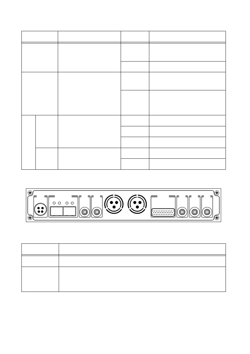
Back Panel
0 1
PWR
REF
IN
PPS
OUT
TRIG
5V DC
REF
OUT
1G/10G ETH
3.3 V +15 dBm
MAX
9-16V DC
7.5 A MAX
SFP+Ports
PCIe x4
TRIG
3.3V
IN
5V MAX
PPS GPS
ANT
–15 dBm
MAX
Table 7. Connector Descriptions
Connector Description
PWR Input that accepts a 9 V to 16 V, 6 A external DC power connector.
1G/10G ETH Ethernet port that accepts 1G SFP modules and 10G SFP+ modules. With a
1G ETH module inserted, the ports accept gigabit Ethernet-compatible
cables (Category 5, Category 5e, or Category 6).
USRP-2950/2952/2953/2954/2955 Getting Started Guide | © National Instruments | 21
 Loading...